Hydraulic wrench control valve systems

Inactive Publication Date: 2002-01-17
POWER TORK HYDRAULICS
View PDF0 Cites 24 Cited by
  • Summary
  • Abstract
  • Description
  • Claims
  • Application Information

AI Technical Summary

Benefits of technology

0006] It is an object of the invention to provide a control syst

Problems solved by technology

Rotation of the drive head results in the rotation of the s

Method used


Image

  • Hydraulic wrench control valve systems
  • Hydraulic wrench control valve systems
  • Hydraulic wrench control valve systems

Examples


Embodiment Construction

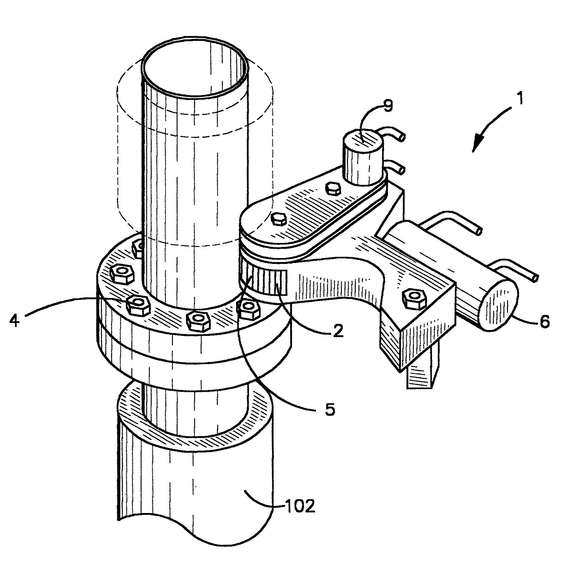
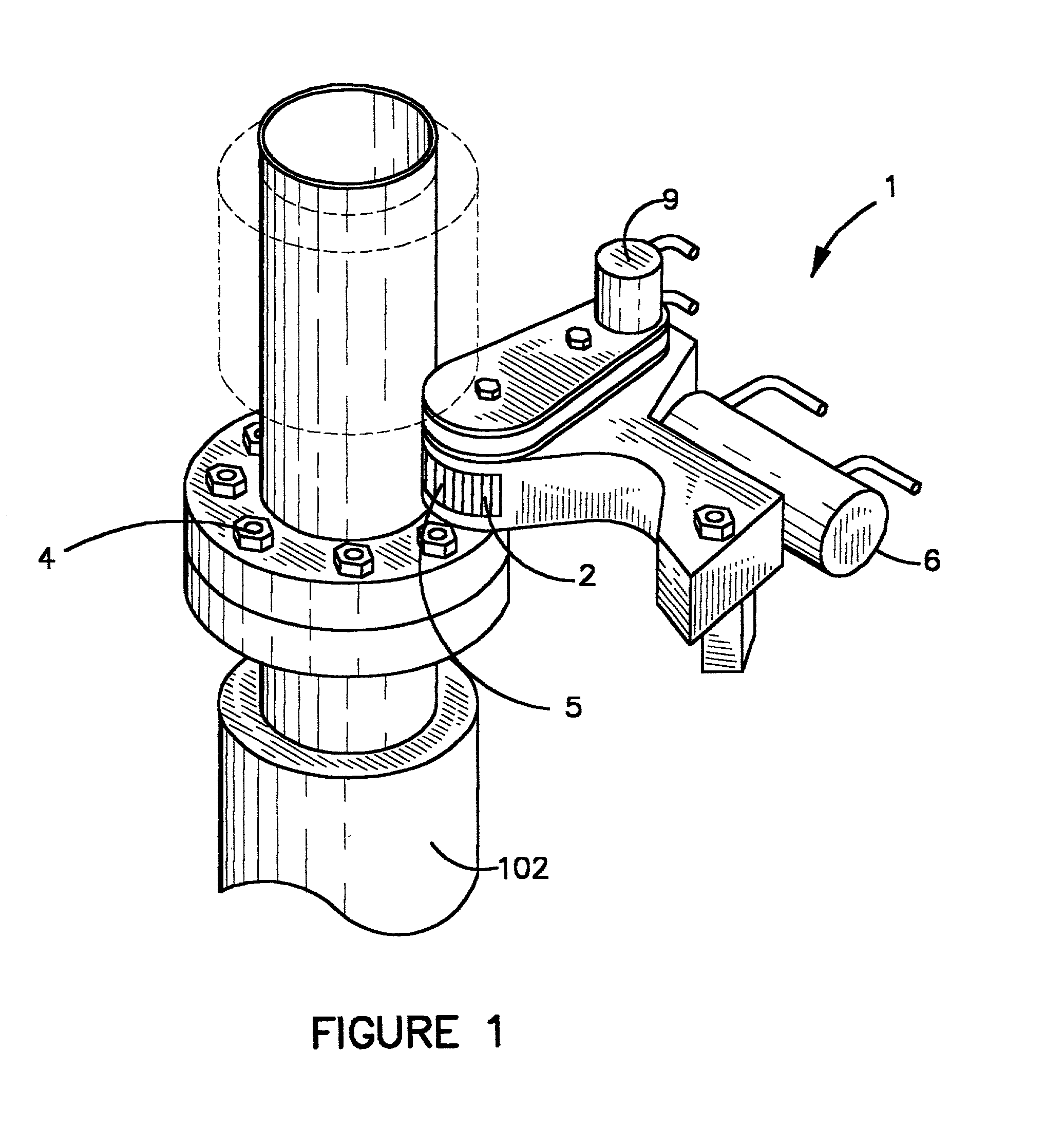
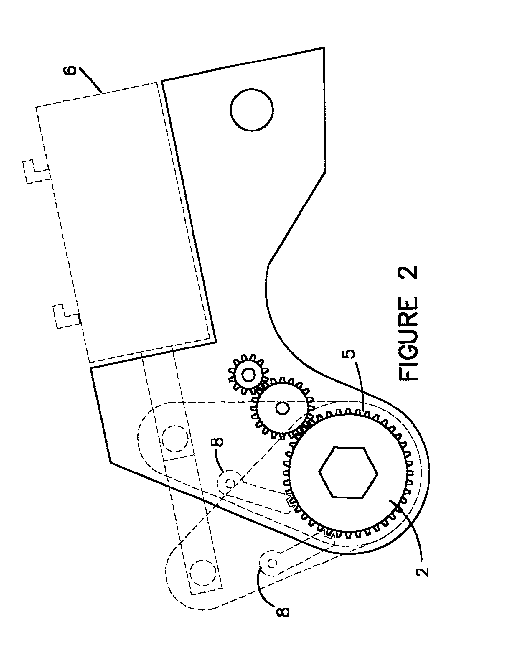
[0021] Hydraulic wrench assembly 1 comprises a drive head 2 having a socket 3 configured to engage a threaded member 4, such as a nut or a bolt. Drive head 2 also comprises a plurality of ratchet teeth 5 radially positioned on drive head 2. Hydraulic wrench assembly 1 further comprises a hydraulic cylinder 6. Hydraulic cylinder 6 is configured to extend and retract a pawl 8 which is positioned to engage ratchet teeth 5 upon extension of pawl 8. When pawl 8 engages ratchet teeth 5, drive head 2, socket 3, and threaded member 4 may be rotated upon further extension of pawl 8, which will either tighten or loosen threaded member 4 depending upon the direction of rotation of drive head 2. Pawl 8 may retracted and extended again, further rotating drive head 3, socket 3, and threaded member 4 until the desired torque is reached or until threaded member 4 is adequately loosened.

[0022] Hydraulic wrench assembly 1 further comprises a spin down motor 9 which is preferably hydraulically driven ...


PUM


Abstract

A wrench assembly including a drive head and an attached socket for engaging a bolt or nut. When the drive head turns, the socket and any engaged threaded member will also rotate. A hydraulic motor and cylinder are also included. The hydraulic motor and cylinder rotate the drive head and socket independently of each other. Typically, the hydraulic motor will rotate the drive head faster than the cylinder but at lower torques. Thus, the hydraulic motor will spin the threaded member down until it is snug, and then the hydraulic cylinder will tighten the threaded member to the desired torque. Alternatively, the hydraulic cylinder may break the threaded member out when it is tight. The hydraulic motor will then spin the loosened threaded member out. Finally, the wrench assembly includes a hydraulic fluid distribution system, including one or more valves that regulate hydraulic fluid flow through the wrench assembly.

Description

BENEFIT OF PROVISIONAL APPLICATION[0001] This application claims benefit of provisional application No. 60 / 201,434, which was filed on May 3, 2000, and which is hereby incorporated by reference in its entirety.BACKGROUND OF THE INVENTION[0002] 1. Field of the Invention[0003] The invention relates to valves in general, hydraulic valves in particular, and especially to a control valve for a hydraulic torque wrench with a hydraulic spin down motor.[0004] 2. Prior Art[0005] The use of hydraulic wrenches to tighten (make up) or loosen (break out) nuts or I bolts in high torque applications, such as the erection of off shore risers is well known. See, e.g., U.S. Pat. No. 4,448,096, which is hereby incorporated by reference. These wrenches are well suited to the task of supplying the high torques needed in these applications, however, they are very slow in turning the bolt or nut being tightened or loosened. This is not a problem when the nut or bolt is snug, as very little additional rota...

Claims


Application Information

Patent Timeline
IPC IPC(8): B25B21/00
CPCB25B21/00B25B21/005
Inventor COLLINS, BOBBYSHIREY, MICHAEL
Owner POWER TORK HYDRAULICS
Why Eureka
Try Eureka