

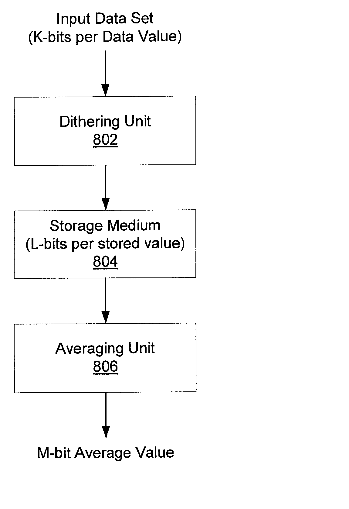
Recovering added precision from L-bit samples by dithering the samples prior to an averaging computation
a technology of l-bit samples and added precision, applied in the field of digital signal processing, can solve the problems of increasing the complexity and amount of data being sent to the display device, affecting the display effect, and integrating graphics processors with a great deal of processing power
- Summary
- Abstract
- Description
- Claims
- Application Information
AI Technical Summary
Problems solved by technology
Method used
Image

Examples
second embodiment
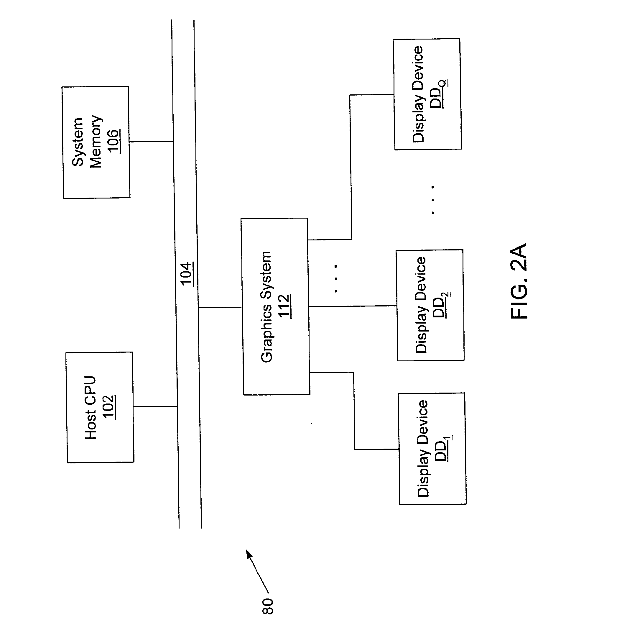
[0067] In a second embodiment, graphics system 112 comprises graphics boards GB(1) through GB(Q / 2) which couple to display devices DD.sub.1-DD.sub.Q in a one-to-two fashion as shown in FIG. 2C. In other words, graphics board GB(I) couples to and generates video signals for two display devices DD.sub.2I-1 and DD.sub.2I where I ranges from 1 to Q / 2.
third embodiment
[0068] In a third embodiment, graphics system 112 comprises graphics boards GB(1) through GB(2Q) which couple to projection devices DD.sub.1-DD.sub.Q in a two-to-one fashion as shown in FIG. 2D. In other words, graphics boards GB(2I-1) and GB(2I) may be daisy chained together to generate a video signal for display device DD.sub.I.
[0069] A wide distribution of "mappings" between graphics boards and display devices are possible. At one end of the distribution, a single graphics board may drive all Q display devices, where the size of Q is limited by the computational bandwidth of the graphics board. At the other end of the distribution, X graphics boards may drive a single projection device. The size of integer X is determined by the input video bandwidth of the projection device. The X graphics boards may be daisy-chained together, and partition the effort of generating the video signal for the single projection device.
[0070] In addition, X graphics boards may map to Q projection dev...
PUM
 Abstract
Description
Claims
Application Information