

Tool for deep rolling of grooves on crankshaft journals or crank pins
a technology for crankshaft journals and crank pins, applied in the direction of grooves, grinding machines, grinding/polishing apparatuses, etc., can solve the problems of reducing unilateral cage wear, and the speed of the wear of work rollers, so as to achieve the effect of increasing the service life of tools
- Summary
- Abstract
- Description
- Claims
- Application Information
AI Technical Summary
Benefits of technology
Problems solved by technology
Method used
Image

Examples
Embodiment Construction
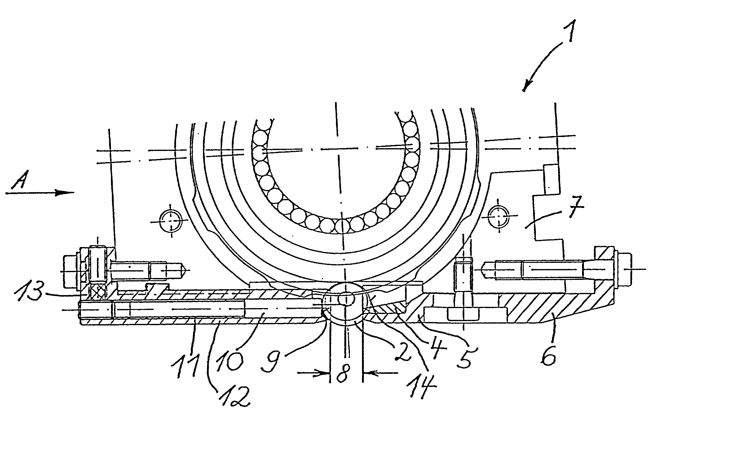
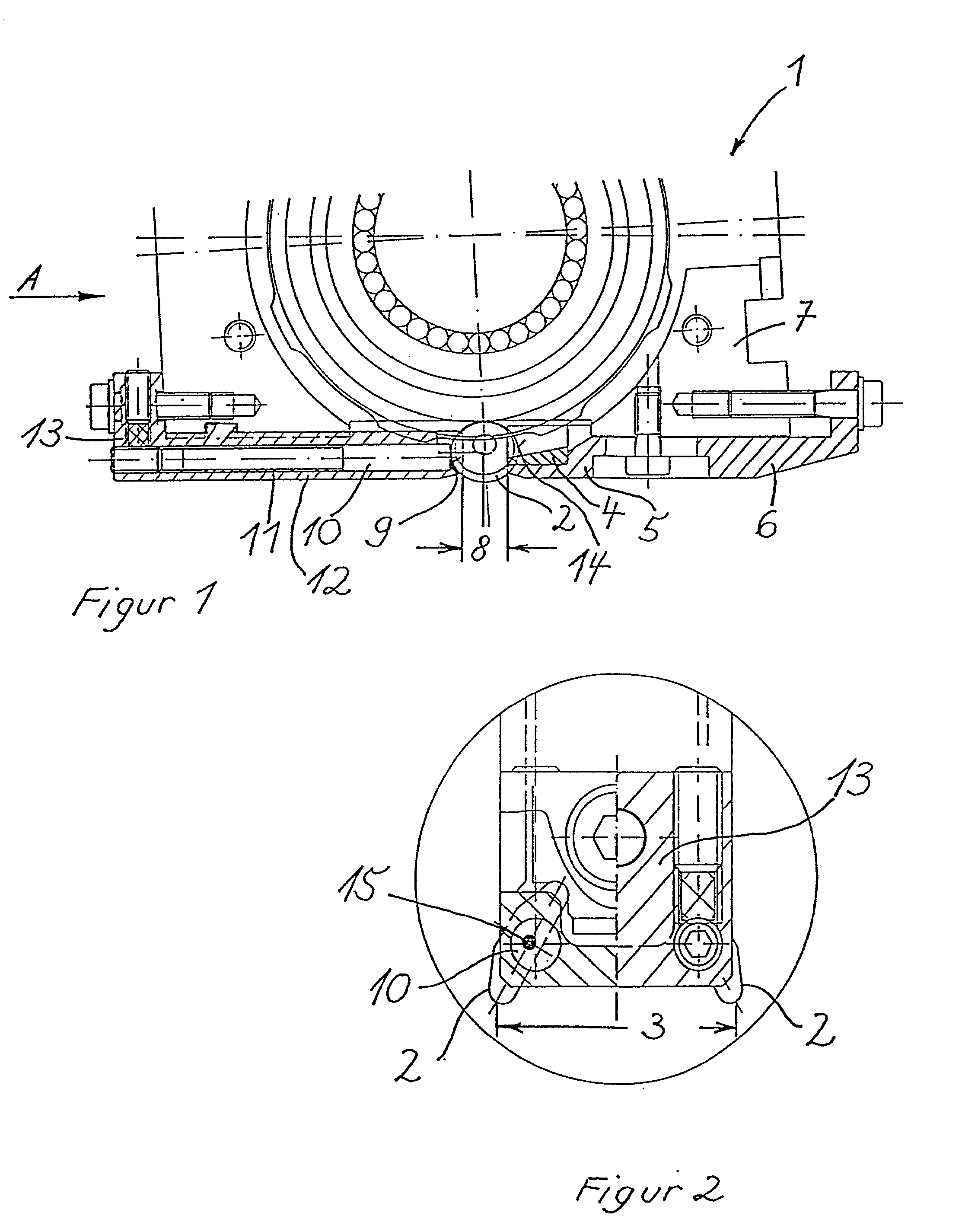
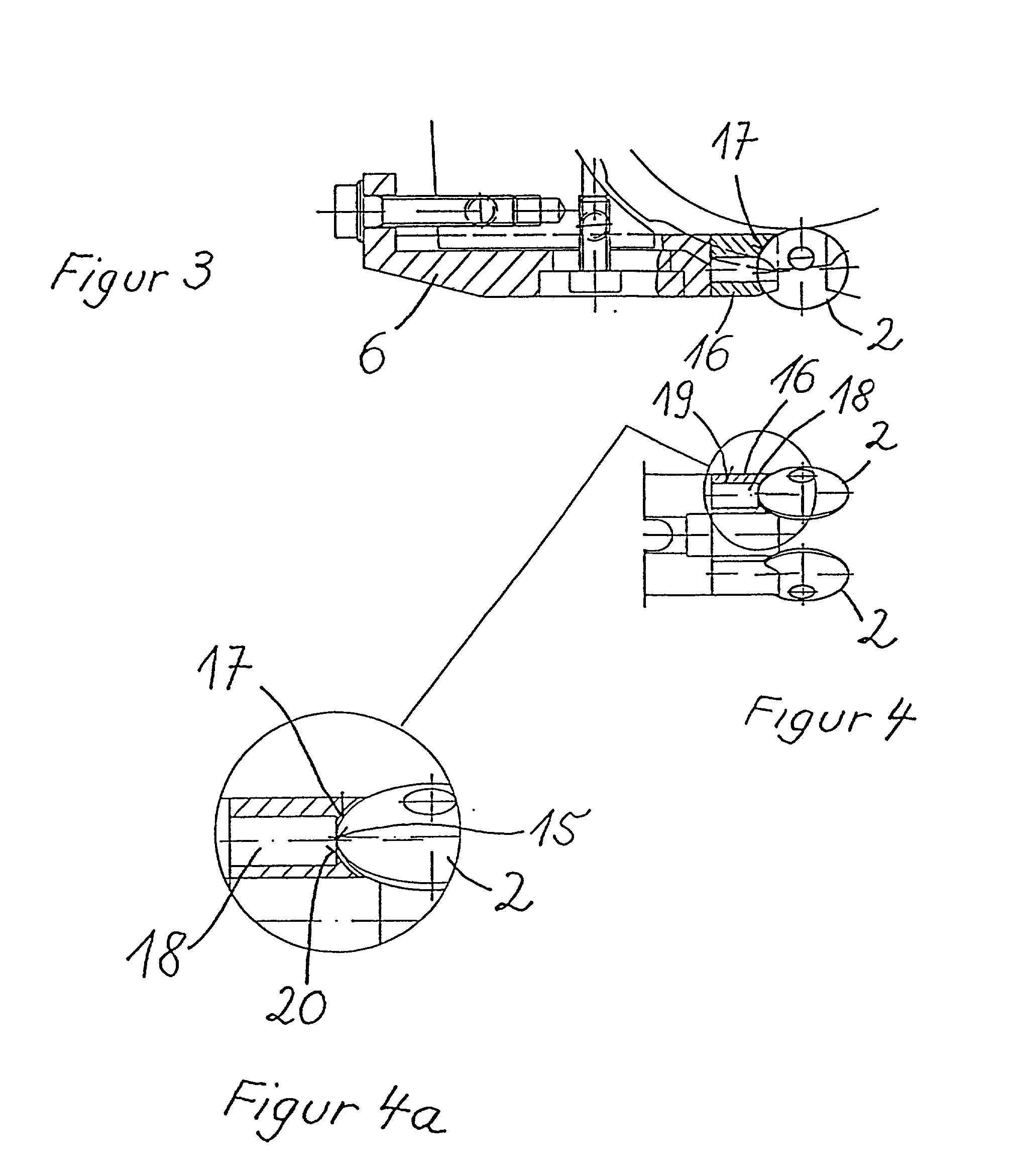
[0018] The deep rolling tool 1 features two work rollers 2 with floating support having a first distance 3 from one another in a common cage 4. The distance 3 equals the distance between the two related grooves (not shown) of a crankshaft to be processed (not shown).
[0019] The cage 4 is guided at the extreme end of the long leg 5 of a first preferably L-shaped tool holder 6 which is connected to the bottom of the tool housing 7, and adjustable.
[0020] On the side opposite the cage 4 and in a second distance 8, each of the two work rollers 2 is supported by the face 9 of a hard pin 10. The pins 10 are each guided in axial bores 11 running in parallel inside the long leg 12 of the opposing, second preferably L-shaped tool holder 13. Therefore, instead of a recess 14 in which the work rollers 2 are guided in the cage 4, on the opposite side the work rollers 2 are only offered a point support 15. Consequently, in the direction of the distance 3 the work rollers 2 are provided with greate...
PUM
| Property | Measurement | Unit |
|---|---|---|
| distance | aaaaa | aaaaa |
| friction | aaaaa | aaaaa |
| elongation | aaaaa | aaaaa |
Abstract
Description
Claims
Application Information