Vehicle power distributor and method of producing the same

Inactive Publication Date: 2002-02-21
AUTONETWORKS TECH LTD +2
View PDF0 Cites 12 Cited by
  • Summary
  • Abstract
  • Description
  • Claims
  • Application Information

AI Technical Summary

Benefits of technology

[0070] As described above, the power distributor according to the present invention is obtained by molding a housing around a device-containing bus bar aggregation having semiconductor switching devices mounted on the bus bar aggregation. Hence, there is an effect that good power distribution in a vehicle can be made by a simple and thin structure. Further, the method of producing the power distributor according to the present invention comprises the steps of: forming a bus bar aggregation; mounting semiconductor devices on the bus bar aggregation; molding a housing around the device-containing bus bar aggregation; and cutting suitable places of the bus bar aggregation after the molding to thereby complete a power distribution circuit. Hence, there is an effect that the power distributor can be produced by simple steps.

Problems solved by technology

Hence, it is difficult to reduce the size greatly.
Particularly there is a large problem in reduction in thickness.
On the other hand, in production process, there is a possibility that a resin housing may be partially melted by heat due to soldering or the like performed for mounting the semiconductor switching devices on the metal plate after the metal plate constituting a power distribution circuit is incorporated in the resin housing.
In order to avoid such melting of the housing, if the metal plate is incorporated in the housing after the semiconductor switching devices are mounted on the metal plate, the work of incorporating the metal plate in the housing is difficult.
Hence, in any case, the assembling work is not easy and the mass-production characteristic is poor.

Method used


Image

  • Vehicle power distributor and method of producing the same
  • Vehicle power distributor and method of producing the same
  • Vehicle power distributor and method of producing the same

Examples


Embodiment Construction

]

[0030] A preferred embodiment of the production method according to the present invention will be described with reference to FIGS. 1 through 8 which are production diagrams and FIG. 9 which is a flow chart.

[0031] 1) Step P1 of Punching AGGREGATION (FIG. 9)

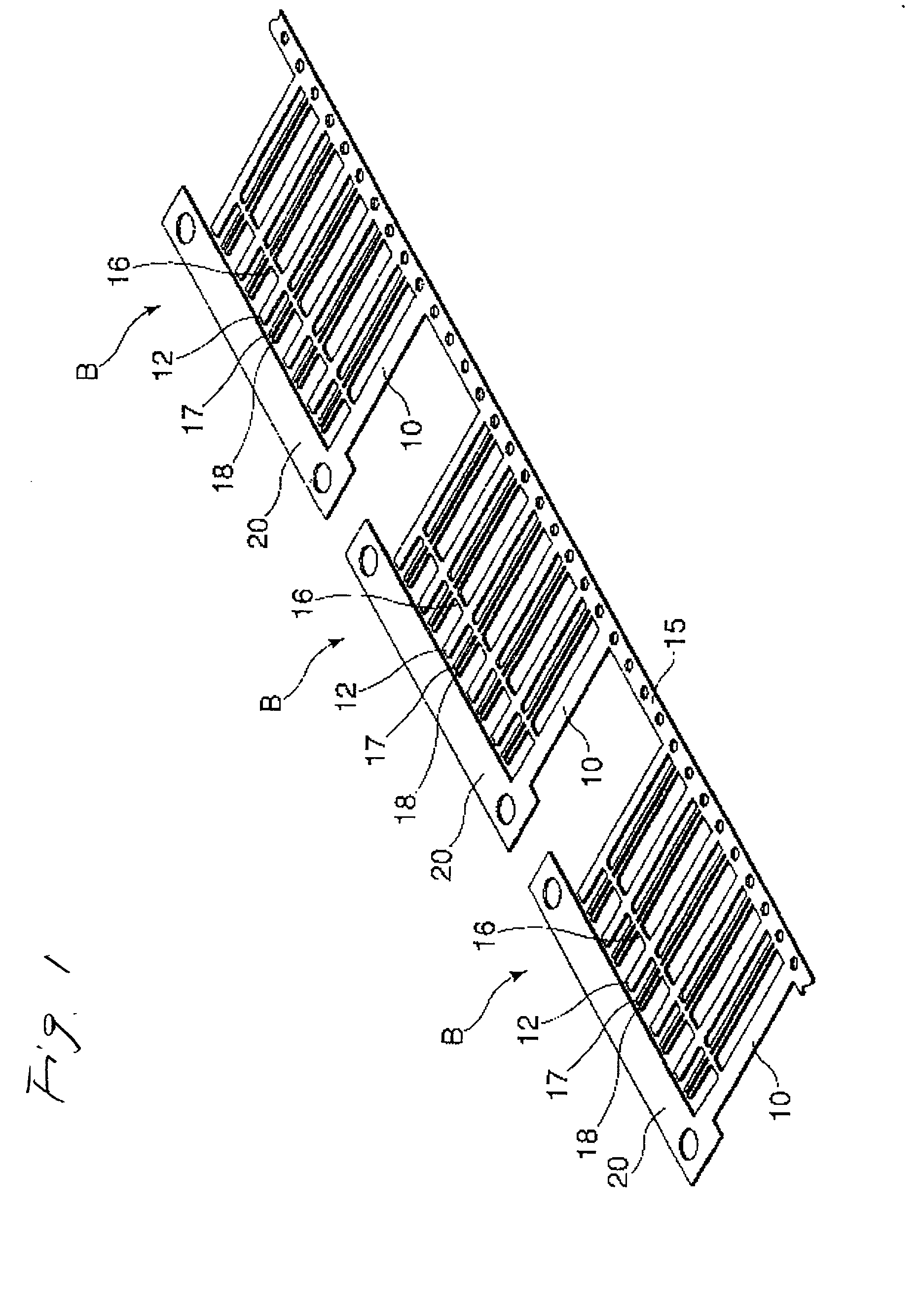
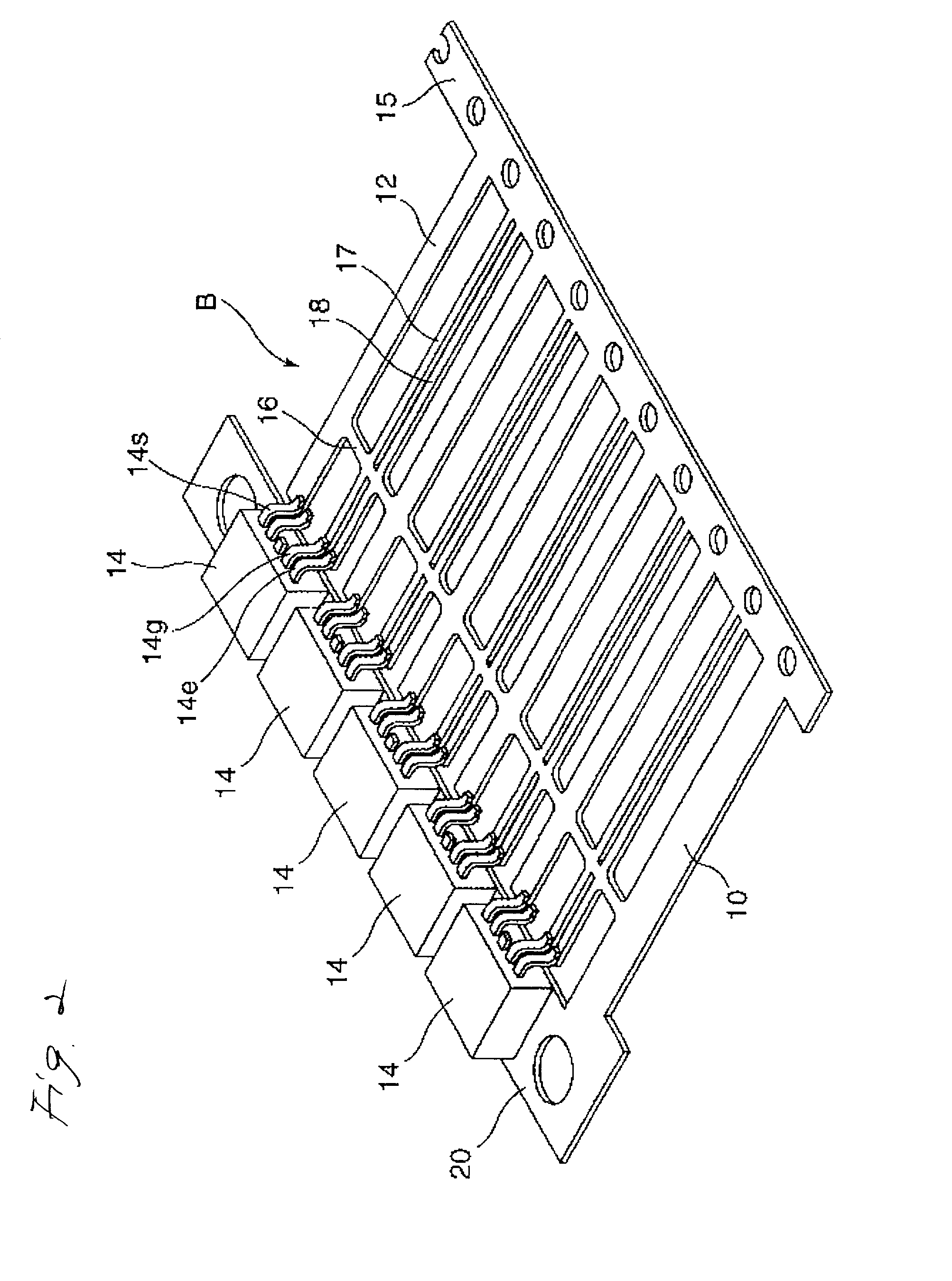
[0032] First, a metal plate excellent in electrically conducting characteristic is punched out by pressing or the like to thereby produce an aggregation of a plurality of bus bars B as shown in FIG. 1 at once.

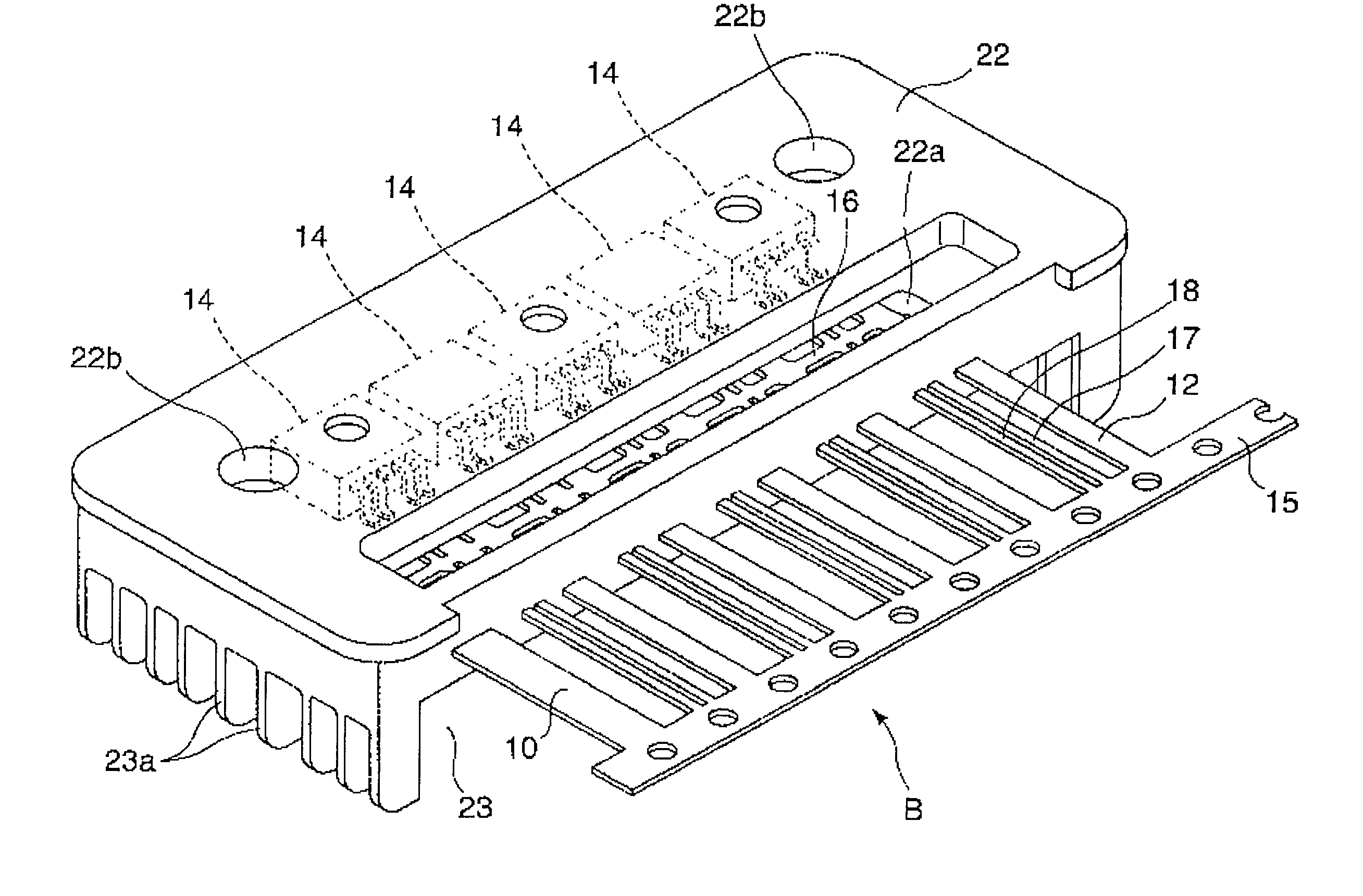
[0033] Each of the bus bar aggregations B shown in FIG. 1 has a single input terminal portion 10, a plurality of (for example, five in FIG. 1) output terminal portions 12, and pairs of signal terminal portions 17 and earth terminal portions 18 arranged near by the output terminal portions respectively so as to be parallel with the output terminal portions. Each of these terminal portions is shaped like a strip of paper. These terminal portions are arranged in parallel with one another at intervals. An FET mount portion (devi...


PUM


Abstract

A power distributor having: a bus bar aggregation B made out of a single plate material; semiconductor switching devices 14 mounted on the bus bar aggregation B; and a housing 22 made out of an electrical insulating material such as resin or the like and molded around the device-containing bus bar aggregation B. A method of manufacturing the power distributor is constituted by the steps of: forming the bus bar aggregation B; molding the housing 22 around the bus bar aggregation B after the semiconductor switching devices 14 are mounted on the bus bar aggregation B; and completing a power distribution circuit after cutting off suitable portions of the bus bar aggregation B after the molding.

Description

[0001] 1. Technical Field[0002] The present invention relates to a power distributor to be mounted on a vehicle, and a method for producing the power distributor.[0003] 2. Related Art[0004] An electric connection box or the like having fuses and relay switches incorporated in a power distribution circuit constituted by a laminate of a plurality of bus bar boards is generally known as a power distributor for distributing electric power given from an on-vehicle power supply into a plurality of on-vehicle loads.[0005] In order to achieve reduction in size of the electric connection box and high-speed switching control, development of a power distributor using semiconductor switching devices such as FETs, instead of the aforementioned relay switches, interposed between input and output terminals has been further advanced in recent years. For example, JP-A-10-126963 discloses a power distributor using a plurality of semiconductor switching devices having drain terminals which are connect...

Claims


Application Information

Patent Timeline
IPC IPC(8): B60R16/02B60R16/023H01L25/07H02G3/16
CPCB60R16/0238H01L2924/0002H01L2924/00
Inventor YAMANE, SHIGEKIISSHIKI, ISAO
Owner AUTONETWORKS TECH LTD
Why Eureka
Try Eureka