Rolling mill and rolling method

Inactive Publication Date: 2002-02-28
HITACHI LTD
View PDF1 Cites 13 Cited by
  • Summary
  • Abstract
  • Description
  • Claims
  • Application Information

AI Technical Summary

Problems solved by technology

Although these gaps are useful for their intended purpose at the time of adjusting the position of the roll in the axial direction or at the time of roll replacement, they will have detrimental effect at the time of rolling the material to be rolled, that is, the roll chocks installed at the ends of the rolls will move due to these gaps, and the rolls become inclined relative to the material being rolled, thereby causing meandering movement of the rolled material or failure of biting of the material at the rolling mill.
These rollers revolve around the roller axis, and during rolling, vibrate the rolling mill at a frequen

Method used


Image

  • Rolling mill and rolling method
  • Rolling mill and rolling method
  • Rolling mill and rolling method

Examples


Example

[0023] In the following, a preferred embodiment of the present invention is described referring to the figures.

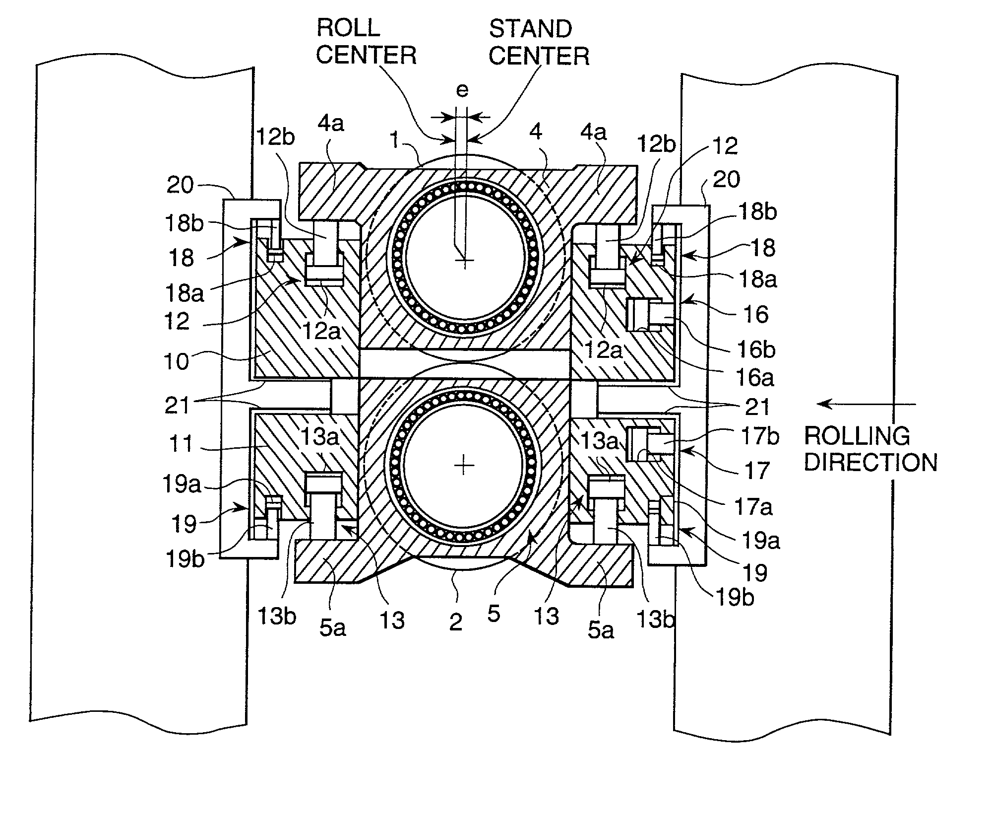
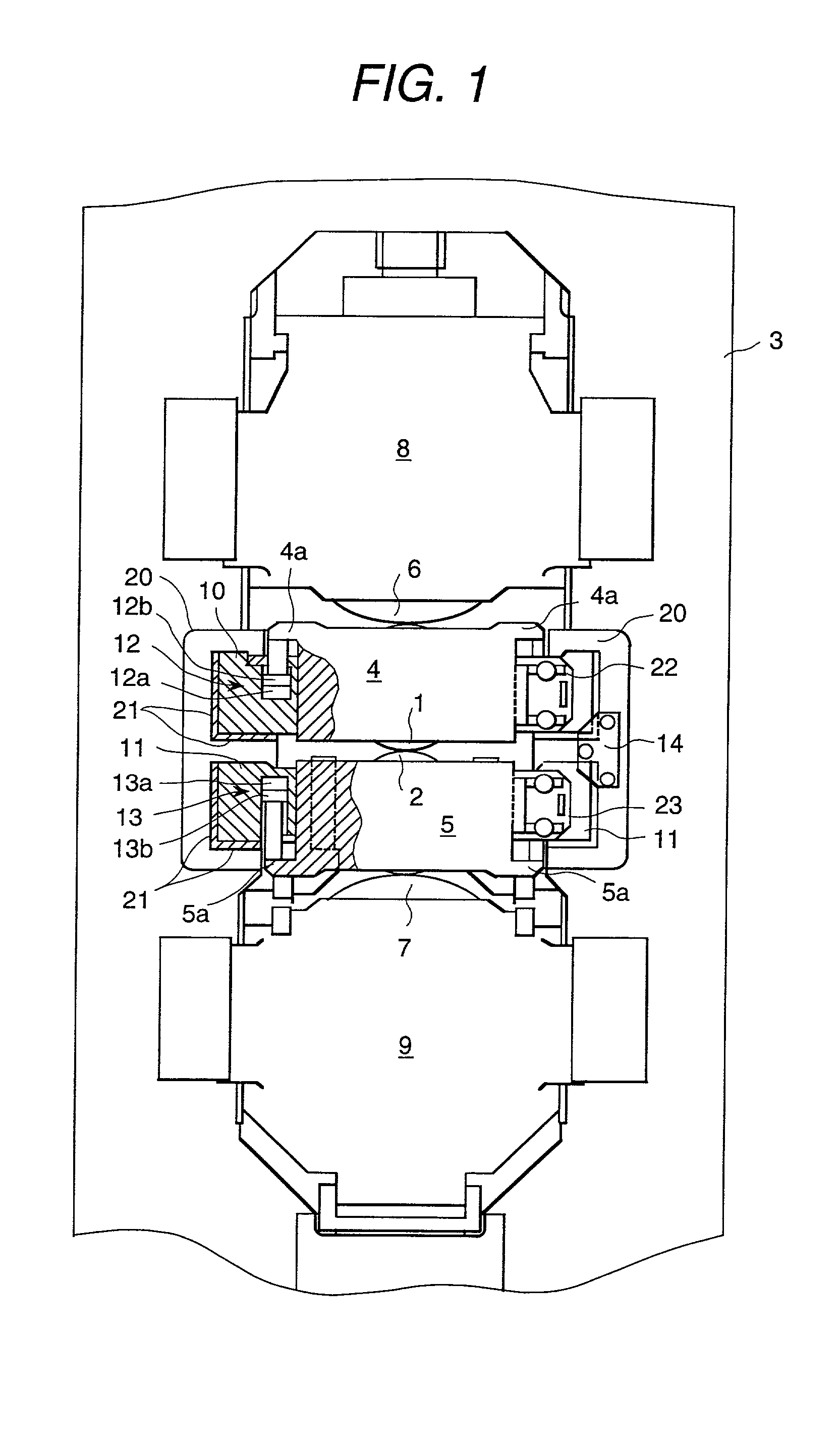
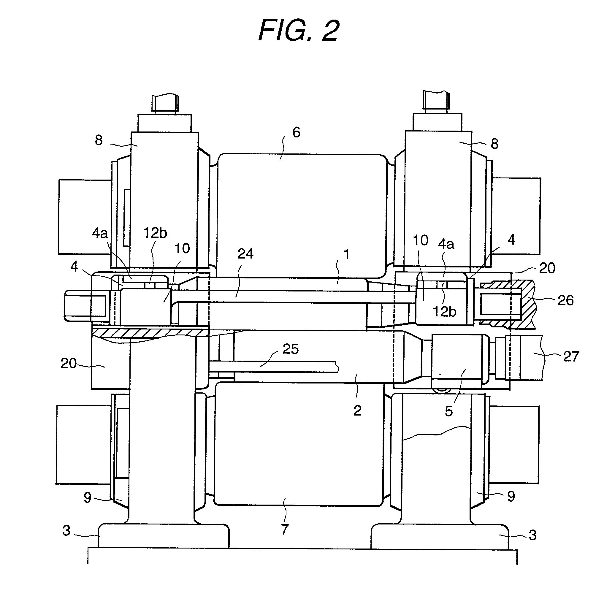
[0024] In FIG. 1 and FIG. 2, the top and bottom work rolls 1 and 2 that roll the material to be rolled are supported at both ends by the work roll chocks 4 and 5 that are held inside the window part of the mill stand (rolling mill housing) 3, and the back-up rolls 6 and 7 in contact with the work rolls 1 and 2 are similarly supported at both ends by the back-up roll chocks 8 and 9 that are held within the mill stand 3. The back-up rolls 6 and 7 and the back-up roll chocks 8 and 9 can move in the up / down direction as in the conventional manner, and are fixed in the direction of the roll axis. The work roll chocks 4 and 5 are formed with a width narrower than the width of the window part of the mill stand 3, and are held and supported by the mill stand 3 via the movable frames 10 and 11 placed almost at the middle of the mill stand in the up / down direction.

[0025] The movable ...


PUM

PropertyMeasurementUnit
Forceaaaaaaaaaa
Flow rateaaaaaaaaaa
Shapeaaaaaaaaaa

Abstract

In a rolling mill in which hydraulic apparatus for controlling the roll balance or the shape of the rolled material are incorporated in movable frames provided separately from roll chocks mounted at each end of the rolls, reducing the roll inclination thereby making it possible to carry out stable rolling, and also reducing the roll vibrations, and making it possible to manufacture products with a high quality. Providing hydraulic apparatus 12 and 13 for controlling the roll balance and the shape of the rolled material inside the movable frames 10 and 11, hydraulic apparatus 16 and 17 that push and restrict the roll chocks 4 and 5 and the movable frames 10 and 11 in the direction of flow of the rolled material relative to the roller stand 3, and the hydraulic apparatus 18 and 19 that push and restrict the movable frames 10 and 11 in the up/down direction relative to the roller stand 3.

Description

[0001] 1. FIELD OF THE INVENTION[0002] The present invention relates to rolling mills and rolling methods, and in particular to, a rolling mill configured so that the rolls can be moved in the direction of the axis of the rolls depending on the width of the material to be rolled, and with a hydraulic apparatus for carrying out control of the roll balance or of the shape of the rolled material being incorporated in a movable frame provided separately from the roll chocks installed at each end of the rolls, and so that said movable frame can be moved in the direction of the roll axis along with the rolls and the roll chock.[0003] 2. DESCRIPTION OF PRIOR ART[0004] Rolling mills for sheet materials are generally constructed so that the rolls can be moved in the direction of the roll axis in order to adjust the position of the rolls in the axial direction depending on the width of the material to be rolled. In such a rolling mill, in the one described in Japanese patent disclosure No. Sh...

Claims


Application Information

Patent Timeline
IPC IPC(8): B21B13/00B21B31/02B21B31/18B21B31/20B21B31/32B21B37/00
CPCB21B31/02B21B31/18B21B31/203B21B31/32B21B37/007B21B2031/206B21B13/00
Inventor HARAKO, TAKEHISAHASHIMOTO, TADASHIKINOSE, RYOHEI
Owner HITACHI LTD
Why Eureka
Try Eureka