Timing chain lubricating structure for engine

a technology of timing chain and lubricating structure, which is applied in the direction of valve drive, lubrication of auxiliaries, lubrication of crankcase compression engines, etc., can solve the problems of increasing the number and limited degree of freedom with which the relief valve can be mounted

Inactive Publication Date: 2002-03-28
HONDA MOTOR CO LTD
View PDF0 Cites 8 Cited by
  • Summary
  • Abstract
  • Description
  • Claims
  • Application Information

AI Technical Summary

Benefits of technology

[0008] In accordance with the above-mentioned arrangement, since the sprocket and the timing chain are lubricated with oil that flows out of the oil drain hole provided at the downstream end of the relief oil passage, it becomes unnecessary to employ an oil jet thus reducing the number of parts. Moreover, since the relief oil passage is formed in the plane of the joined surface of the camshaft holder, the relief oil passage can easily be formed.
[0038] In accordance with the above-mentioned arrangement, since the oil drain hole is provided on the side of the sprocket that is close to the hydraulic control valve that discharges oil to the relief oil passage, the oil passage can be shortened.

Problems solved by technology

The above-mentioned conventional arrangement has the problems that an oil jet is required thus increasing the number of parts, which is a main factor for an increase in the cost, and since the oil jet is formed integrally with the relief valve if the oil jet is placed in a position that is suitable for lubricating the section where the sprocket is meshed with the chain the degree of freedom with which the relief valve can be mounted would be limited.

Method used


Image

  • Timing chain lubricating structure for engine
  • Timing chain lubricating structure for engine
  • Timing chain lubricating structure for engine

Examples


first embodiment

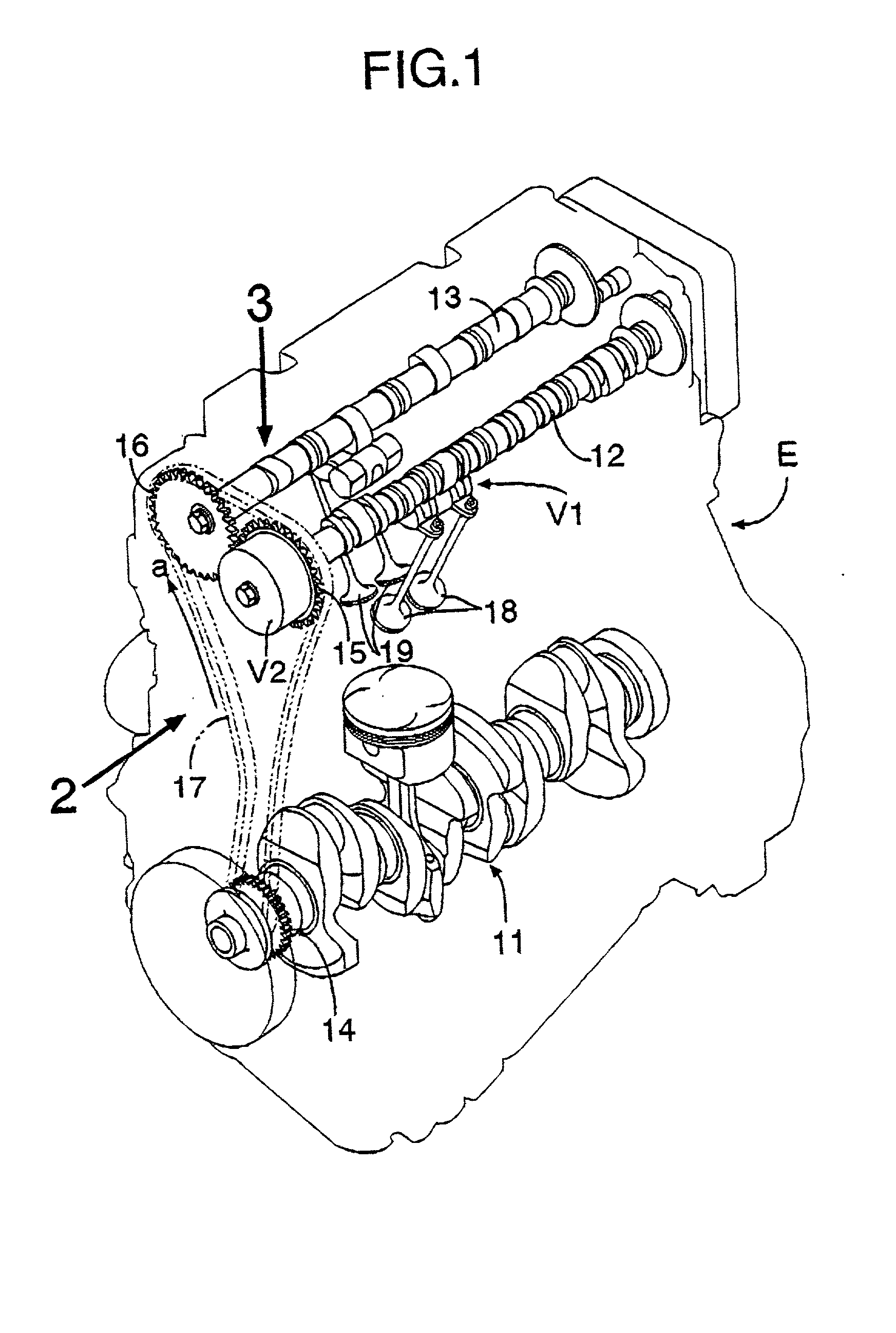
[0056] the present invention is explained below by reference to FIGS. 1 to 13.

[0057] As shown in FIG. 1, a DOHC type in-line four cylinder engine E has a crankshaft 11, an intake camshaft 12 and an exhaust camshaft 13. A timing chain 17 is wrapped around a crankshaft sprocket 14 provided on a shaft end of the crankshaft 11, an intake camshaft sprocket 15 provided on a shaft end of the intake camshaft 12 and an exhaust camshaft sprocket 16 provided on a shaft end of the exhaust camshaft 13. The timing chain 17 is driven in the direction of the arrow a by the crankshaft 11. The intake camshaft 12 and the exhaust camshaft 13 rotate at a speed that is half that of the crankshaft 11. Each of the cylinders has two intake valves 18 driven by the intake camshaft 12 and two exhaust valves 19 driven by the exhaust camshaft 13. The amount of valve lift and the duration for which the valve is open for the two intake valves 18 can be controlled by a first variable valve operating characteristic ...


PUM


Abstract

Sprockets are fixed to ends of camshafts supported in a cylinder head via camshaft holders. A timing chain is wrapped around these sprockets. The relief oil from a hydraulic control valve for controlling a variable valve operating characteristic mechanism passes through an oil passage formed in the plane in which the cylinder head and the camshaft holder are joined and flows out of an oil drain hole, thus lubricating the section where the sprocket is meshed with the timing chain. The section where the sprocket of the camshaft is meshed with the timing chain can thereby be lubricated reliably by a simple structure.

Description

[0001] 1. Field of the Invention[0002] The present invention relates to an engine in which a sprocket is fixed to one end of a camshaft supported in a cylinder head via a camshaft holder and a timing chain is wrapped around the sprocket and, in particular, to a timing chain lubricating structure therefor.[0003] 2. Description of the Related Art[0004] A camshaft of an overhead camshaft type engine is driven by an arrangement in which a sprocket fixed to a shaft end of the camshaft is linked to a sprocket fixed to a shaft end of a crankshaft via a timing chain. A lubricating structure for such a timing chain is known in Japanese Patent Application Laid-open No. 6-146838. The timing chain lubricating structure disclosed in the above-mentioned application has an arrangement in which a relief valve is provided in an oil passage for supplying oil to a hydraulic tappet, and the section where the sprocket is meshed with the chain is lubricated with a jet of oil that issues from an oil jet t...

Claims


Application Information

Patent Timeline
Patent Type & Authority Applications(United States)
IPC IPC(8): F01M9/10F01L1/02F01L1/053F01L1/26F01L1/344F01M1/06F01M1/08
CPCF01L1/02F01L1/022F01L1/053F01L1/267F01L1/3442F01L2001/0537F01L2001/34433F01L2001/3444F02B2275/18
Inventor KOBAYASHI, TOSHIKI
Owner HONDA MOTOR CO LTD
Why Eureka
Try Eureka