Rack for supporting circularly symmetrical containers

a technology for supporting containers and containers, applied in the field of supporting containers, can solve the problems of reducing the number of rows that can be superposed, and affecting the accuracy of storing circularly symmetrical containers in that way, so as to achieve the effect of reducing the modular structure, preventing rotation, and being easy to assembl

Inactive Publication Date: 2002-03-28
BARON TONNELLERIE
View PDF0 Cites 138 Cited by
  • Summary
  • Abstract
  • Description
  • Claims
  • Application Information

AI Technical Summary

Benefits of technology

0027] In a particularly advantageous embodiment of the invention, said second ends of the shafts of said rolling members also form fixing means suitable for connecting the top fixing points of a modular structure to the bottom fixing points of a modular structure above it. Thus, the shafts of the rolling members serve to perform two functions: one is to hold a rolling member in a position that is fixed relative to a structure element; the other is to interconnect two superposed modular structures. As a result, the weakening of the modular structure that would be caused by piercing a curved rod specifically to receive the shaft of the rolling member does not occur, and the rack is simpler to assemble.
0028] Advantageously, said free ends of said hoops constitute the top fixing points of the modular structure, enabling said modular structure to present a space in its top portion suitable for being penetrated, at least between said free ends. Since each of the two free ends of a lower hoop is connec

Problems solved by technology

Nevertheless, given the size of the stacked containers, the number of rows that can be superposed is limited in order to ensure that the assembly is stable.
However, storing circularly symmetrical containers in that way suffers from a major drawback associated with filling or emptying said containers once stacked.
Unfortunately, when the containers are resting on one

Method used


Image

  • Rack for supporting circularly symmetrical containers
  • Rack for supporting circularly symmetrical containers
  • Rack for supporting circularly symmetrical containers

Examples


Embodiment Construction

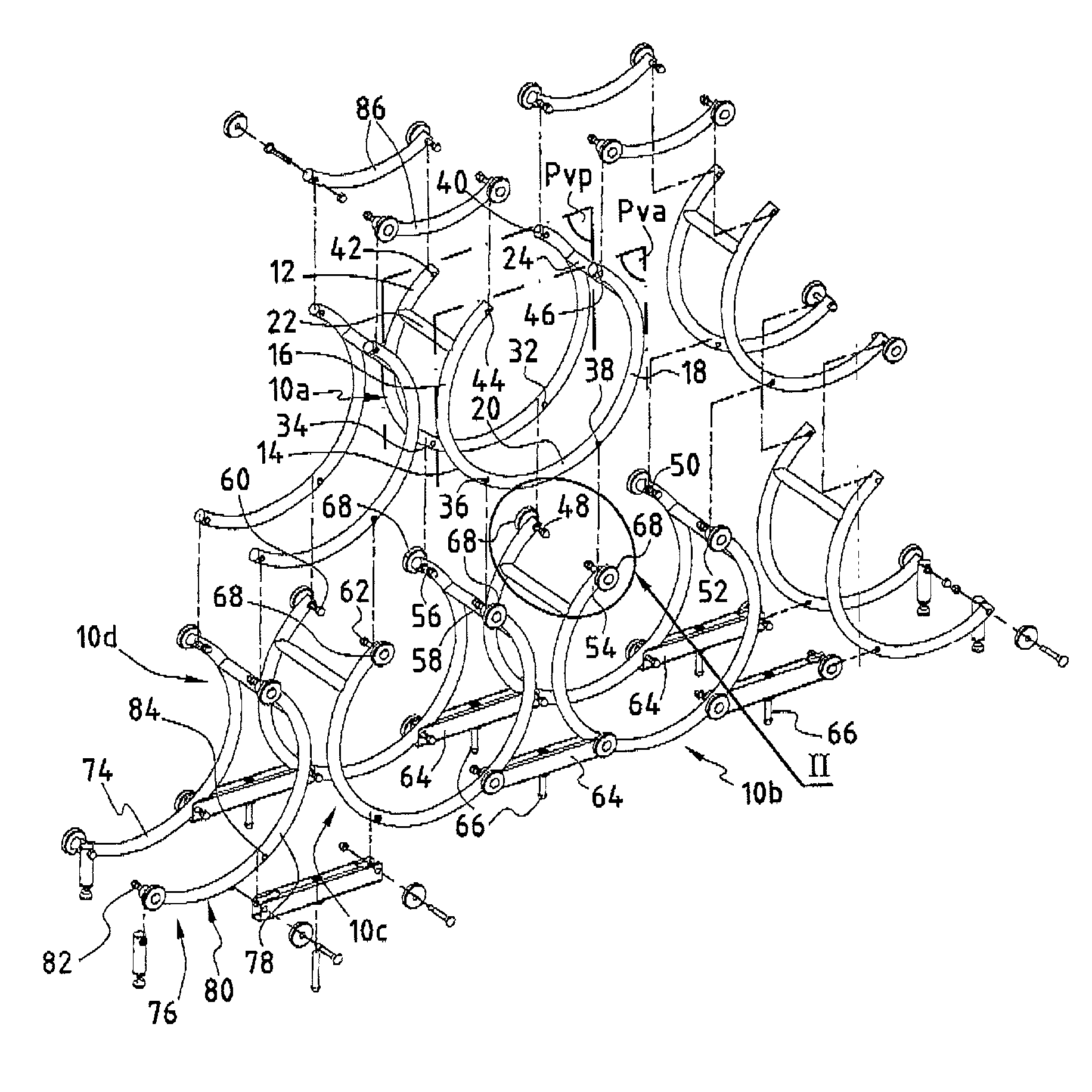
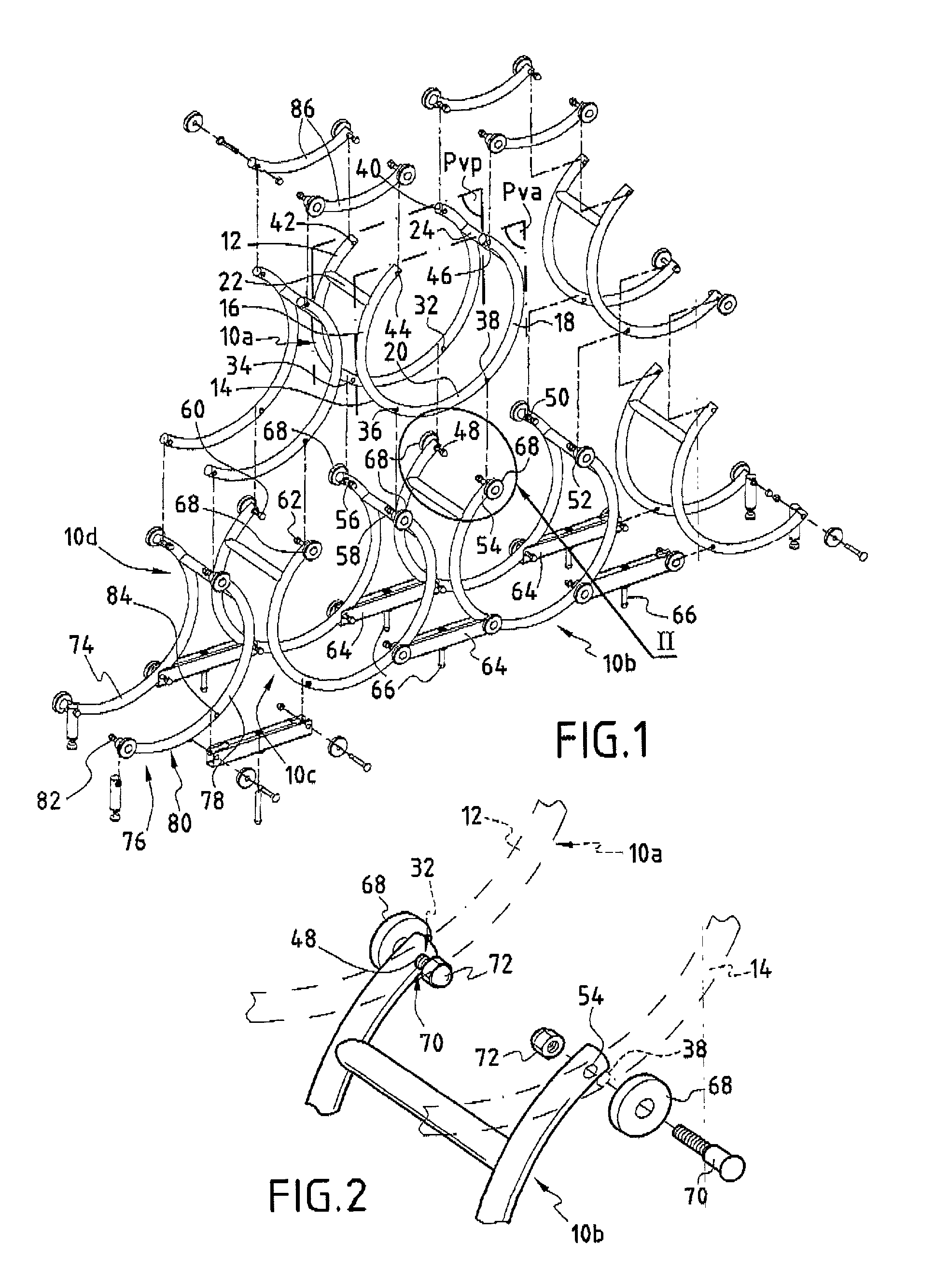
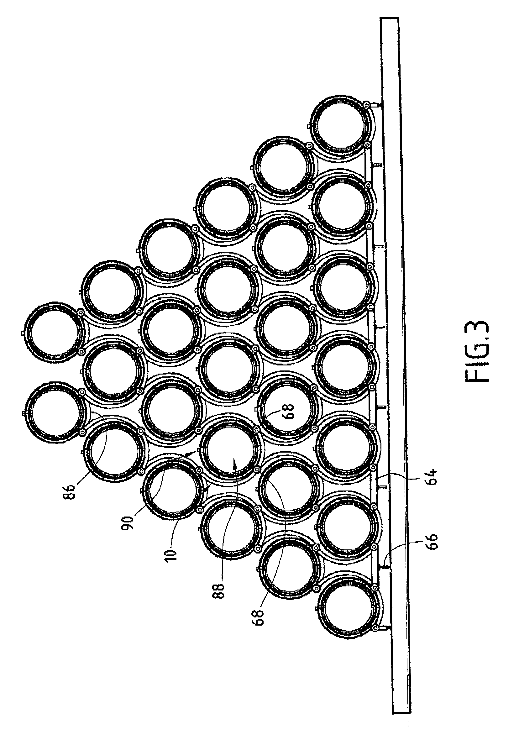
[0036] Reference is made initially to FIG. 1 for a general description of the component elements of the invention and how they are arranged.

[0037] Each modular structure 10 comprises two identical structure elements: a back structure element 12; and a front structure element 14 facing each other and respectively defining a back vertical mean plane Pvp and a front vertical mean plane Pva, which planes are referenced in FIG. 1 for one particular modular structure 10a, the two planes Pvp and Pva being substantially parallel to each other.

[0038] Each structure element comprises two identical vertical arcs 16 and 18 that face each other, with their bottom ends being interconnected by a link arc 20. The arcs 16, 18, and 20 are concave towards the inside. For practical reasons, the structure elements are made as single pieces by curving a tubular section member to form a portion of a hoop.

[0039] The structure elements 12 and 14 are mechanically interconnected near the top by identical link...


PUM


Abstract

The invention relates to a rack for supporting cask-type containers. The rack comprises a plurality of modular structures each suitable for receiving a single container, each modular structure presenting a back vertical mean plane and a substantially parallel front vertical mean plane, and having top fixing points, bottom fixing points, and support means close to said bottom fixing points, said support means being substantially contained in a horizontal plane so as to support a container. The modular structures are connected to one another via their fixing points on a horizontal axis and on a vertical axis so that each upper modular structure straddles two lower modular structures.

Description

[0001] The present invention relates to a rack for supporting containers, and more particularly casks suitable for containing liquids.[0002] Various types of cask are known for containing and storing liquids. In general, they present a first wall portion of generally cylindrical shape closed at each of its two ends by two identical, end-forming circular second wall portions, with the longitudinal axis of such a cask generally intersecting said second wall portions substantially perpendicularly. Filling or emptying orifices are pierced in one or both of the second endwall-forming portions and / or in the first wall portion, generally in the middle thereof.[0003] It is known that circularly symmetrical containers can be stacked together in a vertical plane so that the longitudinal axis of each container is substantially perpendicular to said vertical plane with the second wall portions of the containers coinciding so as to form two vertical mean planes that are parallel to each other.[0...

Claims


Application Information

Patent Timeline
IPC IPC(8): A47B81/00B65D6/08B65G1/02
CPCA47B81/007B65G1/02
Inventor TOMBU, NICOLAS
Owner BARON TONNELLERIE
Why Eureka
Try Eureka