Electronic unit, shield cable connecting structure, connecting method, wires waterproof-connecting structure, and method

a technology of shield cable and connecting structure, applied in the direction of coupling device connection, connection contact member material, coupling protective earth/shielding arrangement, etc., can solve the problems of degrading working efficiency, complex structure, and complicated connection structur

Inactive Publication Date: 2002-04-25
AUTONETWORKS TECH LTD +2
View PDF0 Cites 74 Cited by
  • Summary
  • Abstract
  • Description
  • Claims
  • Application Information

AI Technical Summary

Problems solved by technology

Such operations are troublesome and also the connection structure becomes complicated.
In addition, in order to prevent the waterproof plugs 14 from coming off from the through holes 119, the fixing operation must be applied separately after the press-fitting, so that the working efficiency is degraded and also the structure tends to become complicated.
However, often such connector is complicated in structure to cause a higher cost.

Method used


Image

  • Electronic unit, shield cable connecting structure, connecting method, wires waterproof-connecting structure, and method
  • Electronic unit, shield cable connecting structure, connecting method, wires waterproof-connecting structure, and method
  • Electronic unit, shield cable connecting structure, connecting method, wires waterproof-connecting structure, and method

Examples


first embodiment

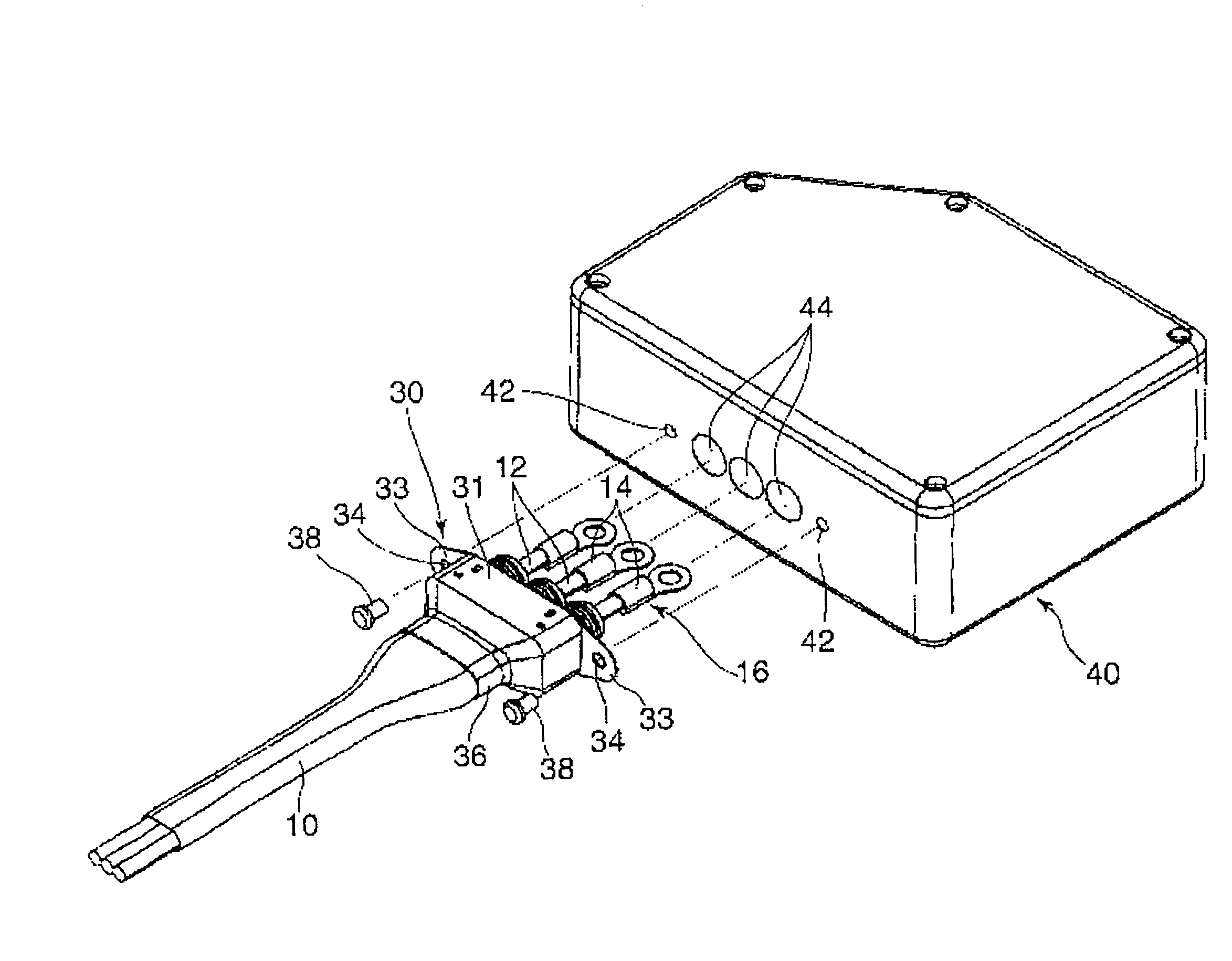
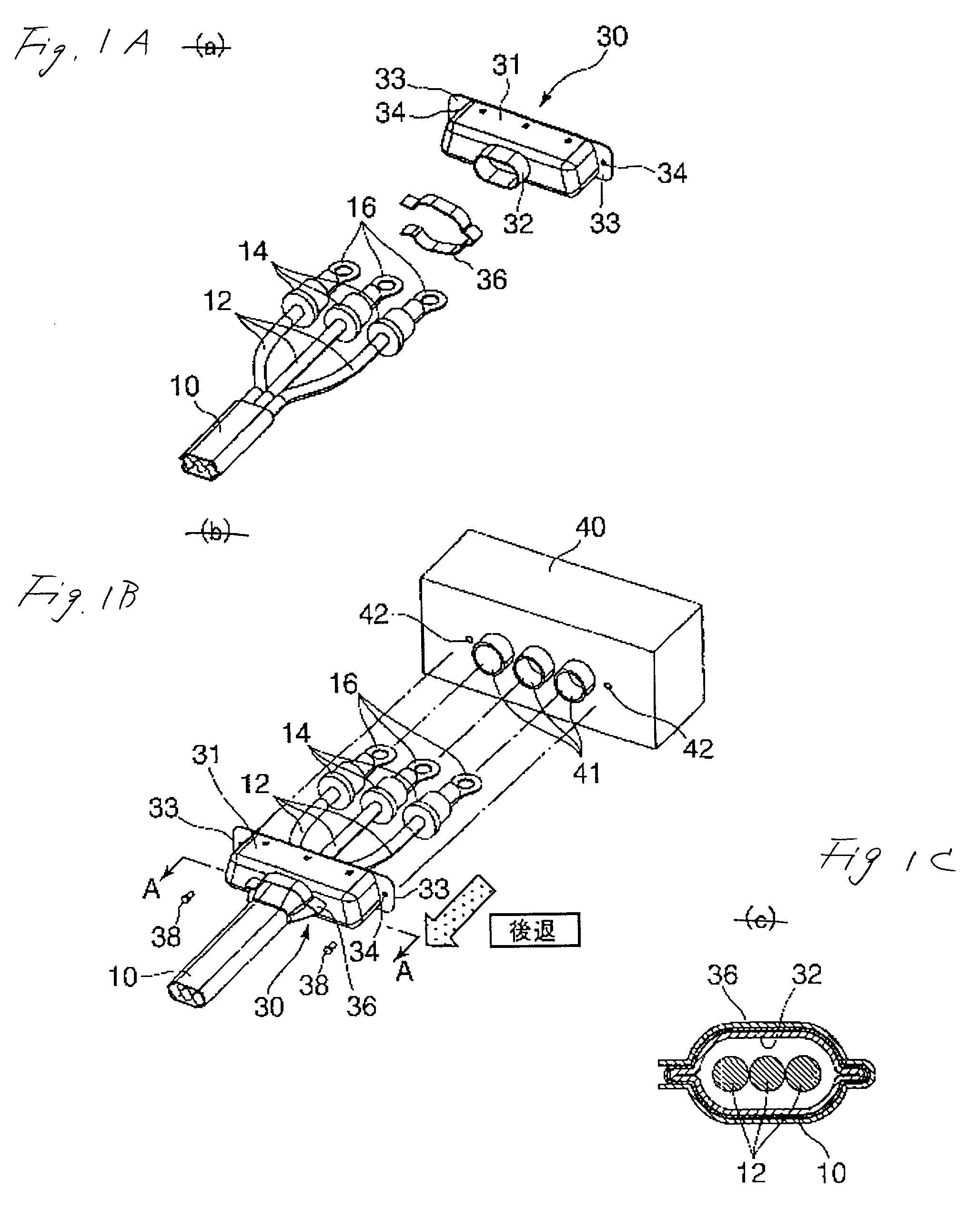
[0052] A first embodiment of the present invention will be explained with reference to FIGS. 1A, 1B, and 1C hereinafter. In this case, same reference symbols are affixed to elements that are equivalent to the constituent elements shown in FIG. 9 and FIG. 10, and their explanation will be omitted.

[0053] A method of connecting the shield cable and the electronic unit according to this embodiment will be given as follows.

[0054] 1) First, the shield cable in which a sufficient clearance is assured between a plurality of wires and the shield lacing 10 is fabricated. In order to fabricate such loose shield cable, for example, the shield lacing 10 may be formed around a group of wires that is constructed by bundling a plurality of wires 12 and dummy wires together, and then the dummy wires may be pulled out. According to this method, the clearance can be formed in an interior of the shield lacing 10 by the volume of the dummy wires. This clearance is prepared to make easy the subsequent 2)...

second embodiment

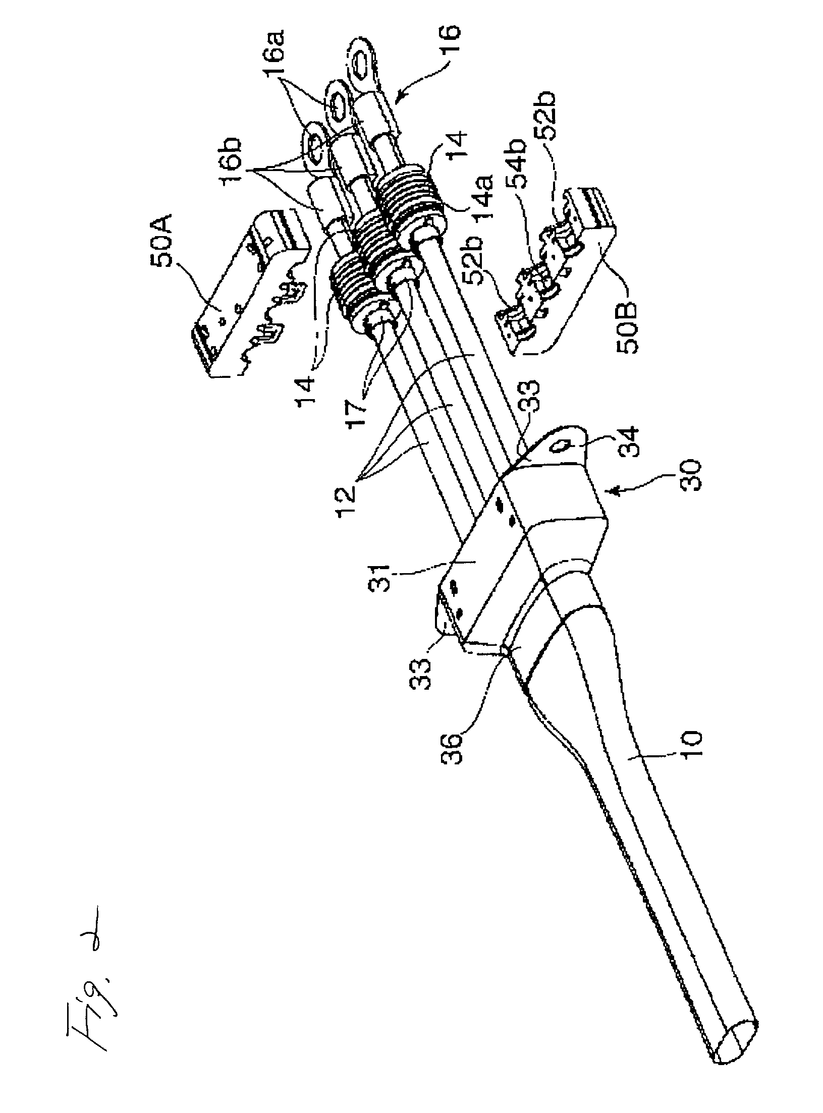
[0062] A second embodiment of the present invention will be shown in FIGS. 2 to 6 hereunder.

[0063] In this embodiment, the cylindrical waterproof plugs 14 are fitted onto respective wires 12 at the position that is slightly later than their end portions, and the terminal tools 16 are directly fixed to the end portions of respective wires 12 at the position that is the front side rather than the waterproof plugs 14. At that time, as shown in figures, the insulation barrel portions 16c of the terminal tools 16 may be press-fitted to the insulating coating portions of the wires 12. Also, a number of peripheral grooves are formed on the surfaces of respective waterproof plugs 14 to form the unevenness, and a peripheral groove 14d is formed at the rear ends of the waterproof plugs 14. In addition, the ring-like waterproof plug fixing tools 17 are arranged at the back of the waterproof plugs 14 and are fixed to the peripheries of the wires 12.

[0064] Then, an upper half holder 50A and a lo...

fifth embodiment

[0078] A fifth embodiment of the present invention will be explained with reference to FIG. 11 to FIG. 14 hereunder. The same reference symbols are affixed to elements equivalent to the constituent elements shown in FIG. 19 to FIG. 10, and their explanation will be omitted.

[0079] In this embodiment, like the example shown in FIG. 19 to FIG. 10, respective wires 12 constituting the shield cable and the electronic unit are connected.

[0080] A unit housing 140 is formed of metal and can be grounded by itself. As shown in FIG. 13 and FIG. 14, this unit housing 140 has a main body 145 that is opened upwardly and a lid 146 for opening / closing the opening, and circuits constructed on a bus-bar substrate 148 are installed in the main body 145. Through holes 144 through which respective wires 12 are passed are provided to be aligned laterally on side walls of the main body 145, and screwed hole 142 that are opened outwardly are formed on left and right side portions of the side walls.

[0081] M...


PUM


Abstract

Terminal tools 16 are fixed to end portions of a plurality of wires 12 that are covered with a shield lacing 10, and a shield case 30 is connected / fixed to the shield lacing 10. End portions of respective wires 12 are inserted into a unit housing 40 of the electronic unit from the outside and connected to circuits in the unit housing 40, and then connected portions between respective wires 12 and a unit housing 40 are covered with the shield case 30 from the outside by fixing the shield case 30 to an outer surface of the unit housing 40. Also, the shield case 30 and the shield lacing 10 are brought into the state that they can be grounded via the unit housing 40.

Description

[0001] 1. Technical Field[0002] The present invention relates to a structure and a method for connecting a shield cable, in which a plurality of wires are covered with a shield lacing, to an electronic unit installed in the vehicle.[0003] Further, the present invention relates to a structure and a method for connecting a plurality of wires to an electronic unit installed in the vehicle in the waterproof condition.[0004] 2. Related Art[0005] If the wires must be shielded from other circuits in the situation that the cable is connected electrically to the electronic unit (e.g., the control box of the electric motor) installed in the vehicle, the shield cable is employed as the cable. As the shield cable, the cable in which respective wires are covered with the flexible shield lacing (e.g., copper lacing) is often employed. An example of the method of connecting such shield cable to the electronic unit in the prior art will be explained with reference to FIG. 9 and FIG. 10 hereunder.[0...

Claims


Application Information

Patent Timeline
Patent Type & Authority Applications(United States)
IPC IPC(8): H01R4/34H01R9/24H01R13/52
CPCH01R4/34H01R2201/26H01R13/5205H01R9/24
Inventor OOTA, KOUJIHIRAI, HIROKIKUMAZAWA, YOSHIHIROSAKAI, SHIGEKI
Owner AUTONETWORKS TECH LTD
Why Eureka
Try Eureka