
Distributed admission control

a technology of distributed admission and control, applied in the field of telecommunications, can solve the problems of admission control function that will not work, admission control errors, and significant negative impact on the quality of existing connections

Inactive Publication Date: 2002-04-25
TELEFON AB LM ERICSSON (PUBL)
View PDF8 Cites 44 Cited by
  • Summary
  • Abstract
  • Description
  • Claims
  • Application Information

AI Technical Summary

Benefits of technology

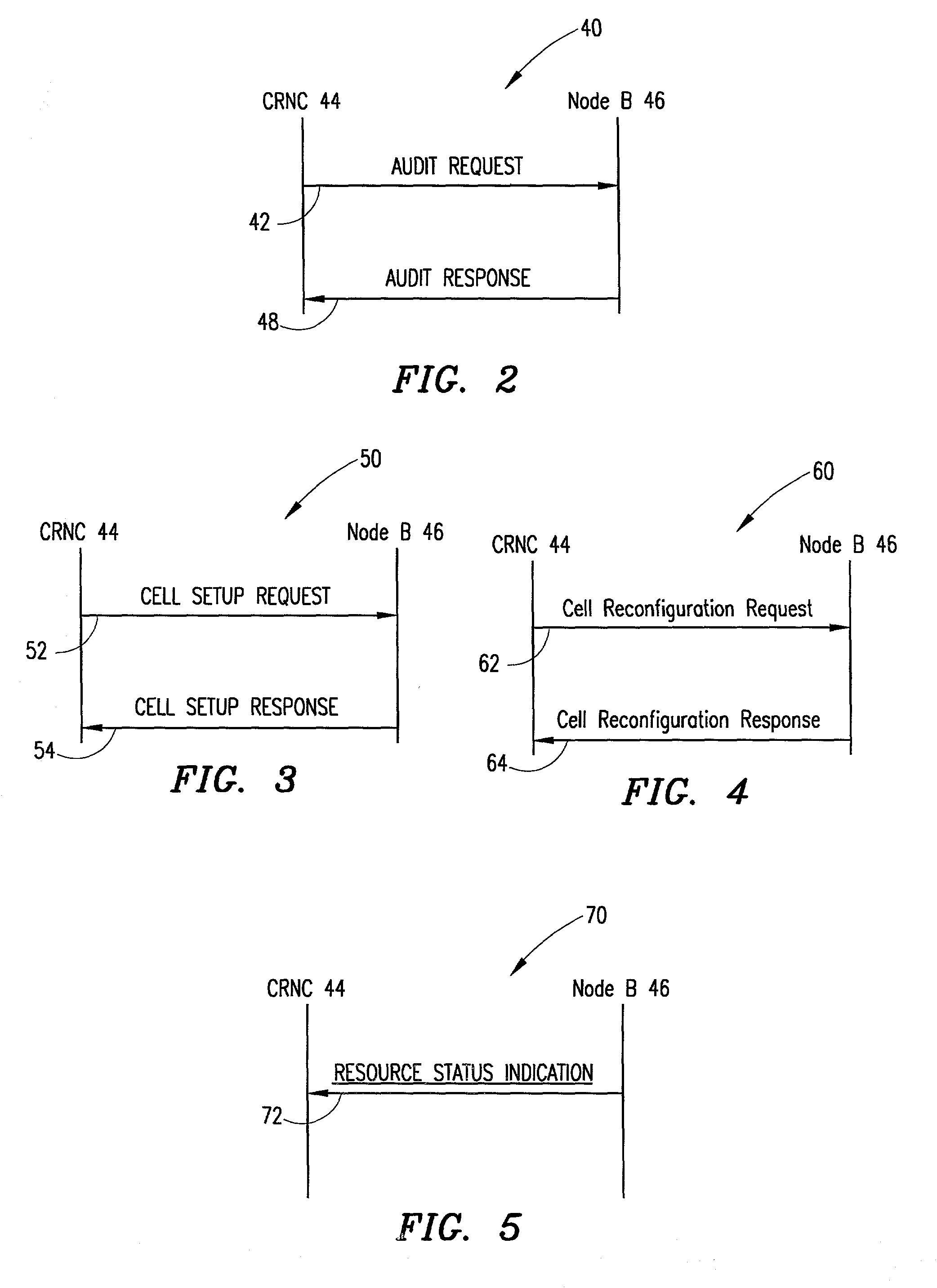
[0010] With the present invention, a plurality of the Node B internal resources for admission control are controlled by the Node B. As a result, the admission control function will not be dependent on errors from fragmentation or require hardware implementation in the Node B. At the same time, certain of the admission control functions are retained with the CRNC so that various network related requirements can remain satisfied.
[0012] In general, the present invention provides admission control procedures for a mobile communications system, particularly a 3.sup.rd generation mobile communications system, that distributes the admission control function between the CRNC and the Node B so as to eliminate errors that may occur in the admission control due to fragmentation; while, at the same time, fully satisfying network requirements relating to the admission control.

Problems solved by technology

If, for example, the system load is very high such that admitting a new connection may have a significant negative impact on the quality of existing connections; the decision process might result in a decision to not admit the new connection.
The capacity credits and consumption laws are both service and hardware dependent, and cannot take fragmentation into account; and this can result in errors in the admission control.
Consequently, even in a single vendor environment, the admission control function will work badly with regards to Node B internal resources; whereas, in a multi-vendor environment, it becomes almost impossible to secure admission control with respect to Node B internal resources.
As a result, either the reservation for certain connection priorities, such as incoming handovers and emergency calls, cannot be guaranteed; or rejection of non-priority calls can be made unnecessarily.

Method used


Image

  • Distributed admission control
  • Distributed admission control
  • Distributed admission control

Examples


Embodiment Construction

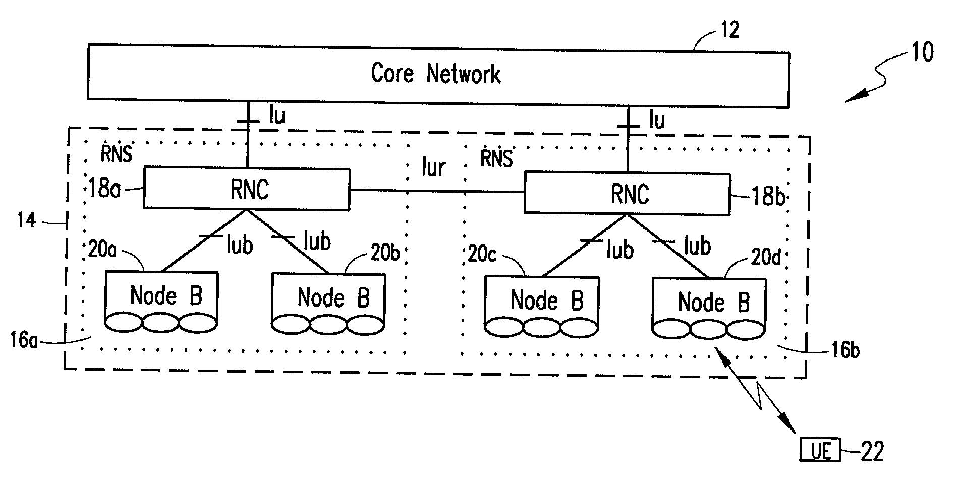
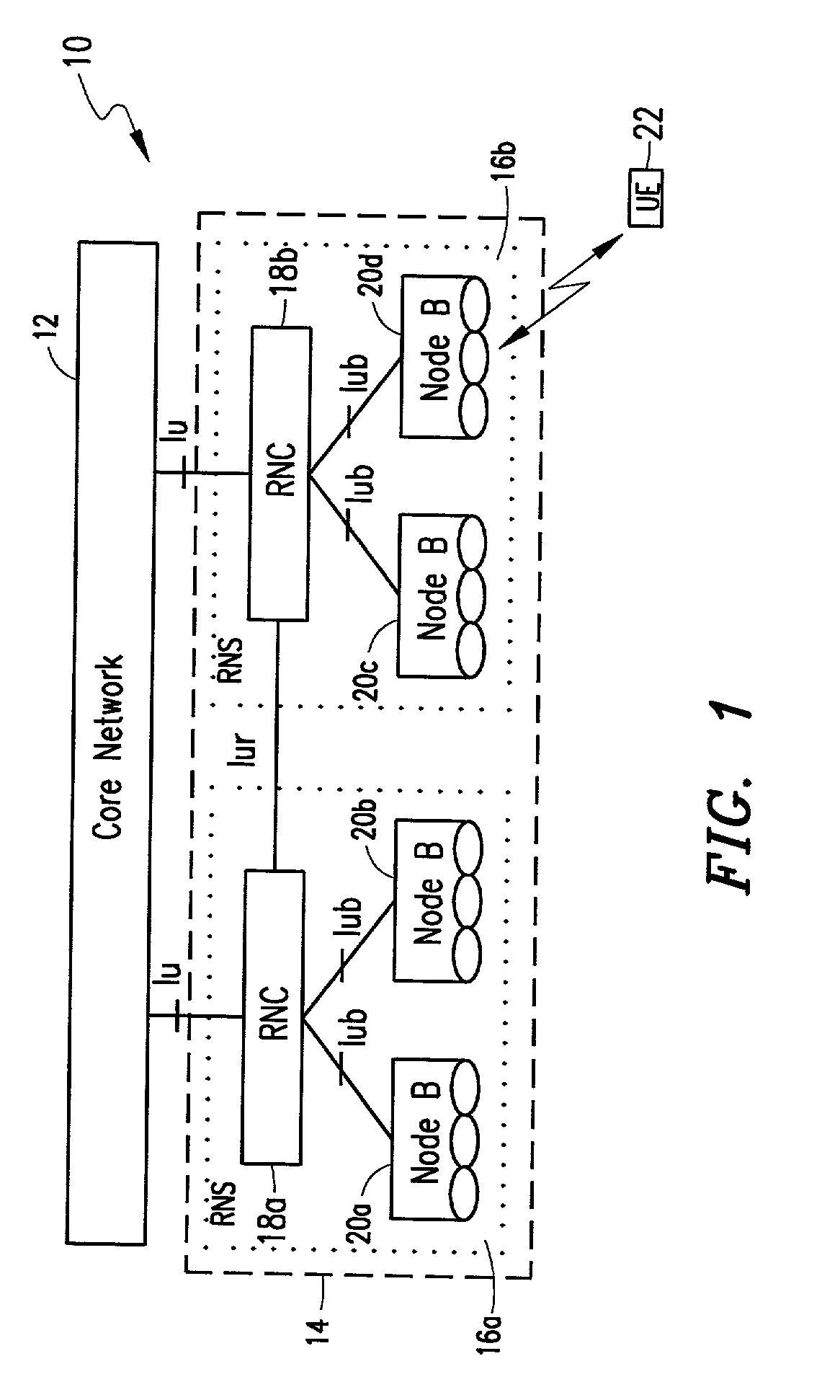
[0022] FIG. 1 is a block diagram of an exemplary mobile communications network; and, in particular, an exemplary 3.sup.rd generation mobile communications network that can be used to implement embodiments of the present invention. More particularly, FIG. 1 illustrates a Universal Mobile Telephony System (UMTS), generally designated by reference number 10, which is configured in accordance with the 3.sup.rd Generation Partnership Project (3GPP) technical specifications.

[0023] UMTS 10 includes a Core Network 12, and a Universal Terrestrial Radio Access Network (UTRAN) 14. UTRAN 14 includes one or more Radio Network Subsystems (RNSs), such as RNSs 16a and 16b. The RNSs 16a and 16b each include an RNC (Radio Network Controller) 18a and 18b, respectively, and related Node Bs 20a, 20b and 20c, 20d, respectively.

[0024] The Core Network 12 enables subscribers to access services from a network operator. An RNS can function in a UTRAN as, for example, the access part of the UMTS network; and ...


PUM


Abstract

A mobile communications system has a radio network controller and a Node B coupled to the radio network controller, the Node B being operable to control a plurality of its Node B internal resources for admission control. Admission control is moved from a controlling radio network controller (CRNC) to the Node B so as to avoid possible errors relating to fragmentation that occur in systems in which the CRNC controls admission. To support network related requirements, such as reserving capacity for high priority calls and incoming handovers, the CRNC informs the Node B about the reservations that shall be applied, and the Node B configures the admission control algorithm in accordance with the reservations.

Description

[0001] This application claims the benefit of copending U.S. Provisional Application Ser. No. 60 / 237,156 filed Oct. 2, 2000.[0002] 1. Field of the Invention[0003] The present invention relates generally to the telecommunications field; and, more particularly, to a 3.sup.rd generation mobile communications system in which a Node B of the system is operable to control certain of its Node B internal resources for admission control.[0004] 2. Description of the Prior Art[0005] One implementation of the so-called 3.sup.rd generation mobile communications system is the Universal Mobile Telephony System (UMTS). UMTS is a distributed system in which each node is supposed to manage its node internal resources by itself. In practice, however, some functions are required to be either centralized or distributed; and one such function is the admission control function.[0006] The admission control function is basically the decision process for admitting or not admitting a new connection. If, for e...

Claims


Application Information

Patent Timeline
Patent Type & Authority Applications(United States)
IPC IPC(8): H04L12/56H04W28/16H04W72/00
CPCH04W72/0433H04W28/16H04W72/29
Inventor PETERSEN, ROBERT
Owner TELEFON AB LM ERICSSON (PUBL)
Learn More