
Organizing and combining a hierarchy of configuration parameters to produce an entity profile for an entity associated with a communications network

a technology of configuration parameters and entity profiles, applied in the field of organization and combining a hierarchy of configuration parameters to produce an entity profile for an entity associated with a communications network, can solve the problems of information loss, time-consuming and costly process of manual reconfiguration,

Inactive Publication Date: 2002-05-16
PINGTEL CORP
View PDF16 Cites 68 Cited by
  • Summary
  • Abstract
  • Description
  • Claims
  • Application Information

AI Technical Summary

Benefits of technology

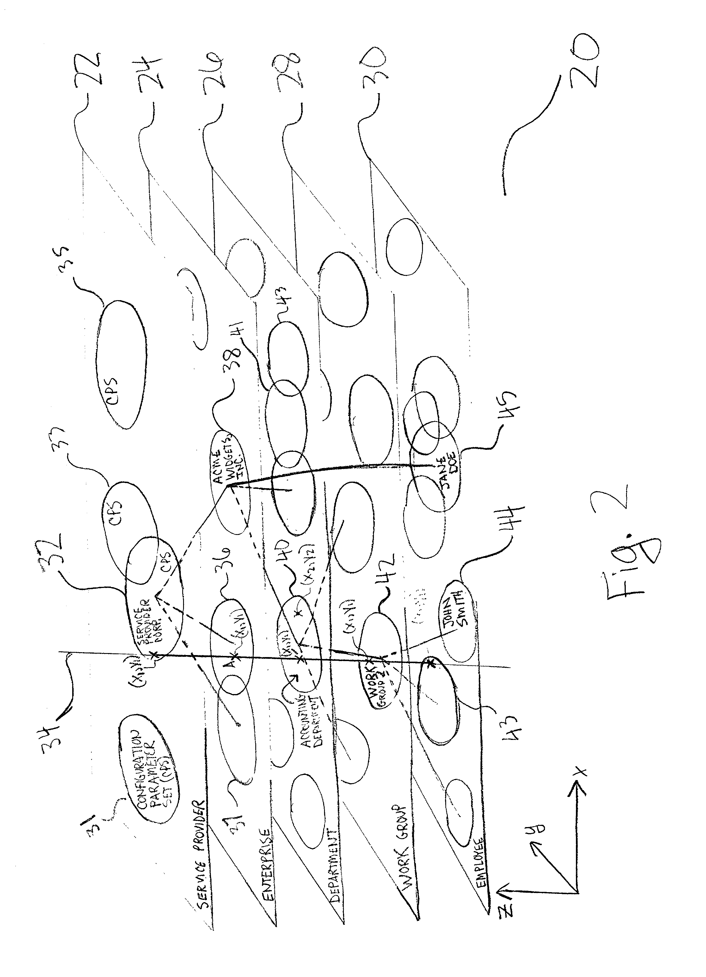
0029] Provided herein is method of and system for organizing a hierarchy of sets of one or more parameters, for example, configuration parameters, maintaining the plurality of parameter sets, and combining two or more of the plurality of parameter sets to produce a single set of configuration parameters (i.e., an entity profile) for an entity, where such entity may be associated with a communications network. The generated entity profile may be used to configure a device, for example, a network device, associated with the entity.

Problems solved by technology

A first drawback of this technique for defining values for configuration parameters is that after the ND is installed, many of the values of configuration parameters may be fixed, and little or no reconfiguration of the ND may be accomplished without manually re-defining, on the ND itself, the values of the many configuration parameters.
Although this may not be significant for small communications networks, as the number of NDs grows, manual reconfiguration becomes a timely and costly process.
Another drawback of this technique is that although there may be multiple entity groups associated with an entity, each entity group corresponding to a level of a hierarchy, only a single set of configuration parameters and their defined values is persisted and maintained for the entity.
This information may be lost after the value of the configuration parameter is set manually.
Although such a technique for changing the value of one or more configuration parameters for one or more NDs may save time and cost over manual configuration and reconfiguration, such a technique does not remedy the drawbacks described above with maintaining only a single set of configuration parameters associated with an entity and not maintaining information about the relationship between the values defined for the one or more configuration parameters of the single set and the hierarchy of entity groups that may have influenced the current values of the configuration parameters.

Method used


Image

  • Organizing and combining a hierarchy of configuration parameters to produce an entity profile for an entity associated with a communications network
  • Organizing and combining a hierarchy of configuration parameters to produce an entity profile for an entity associated with a communications network
  • Organizing and combining a hierarchy of configuration parameters to produce an entity profile for an entity associated with a communications network

Examples


Embodiment Construction

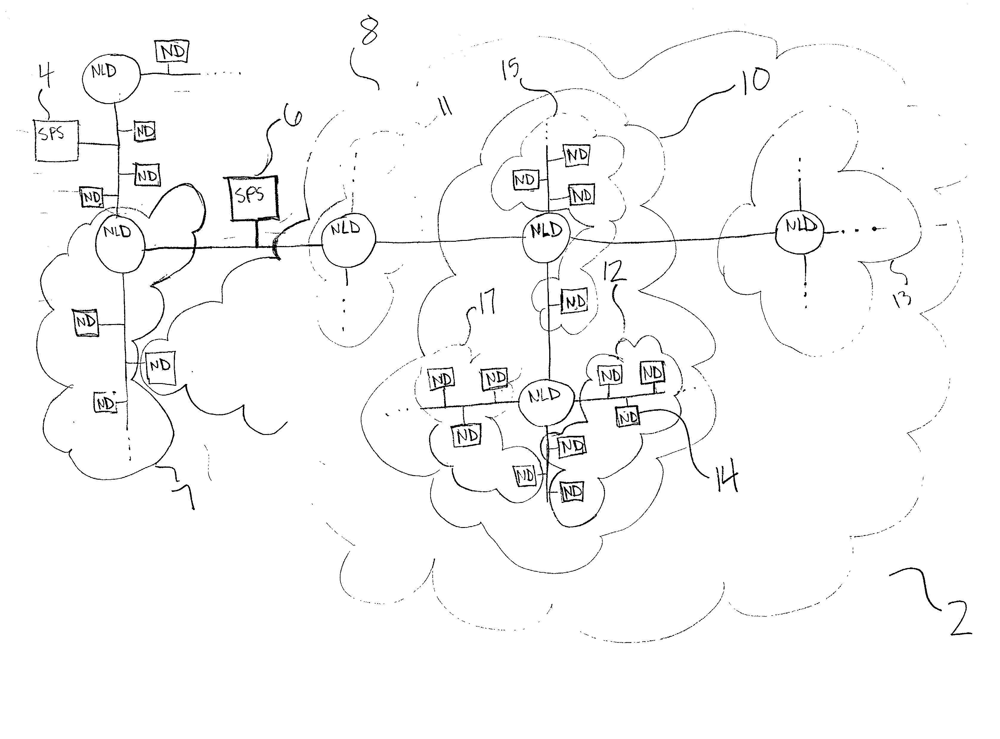
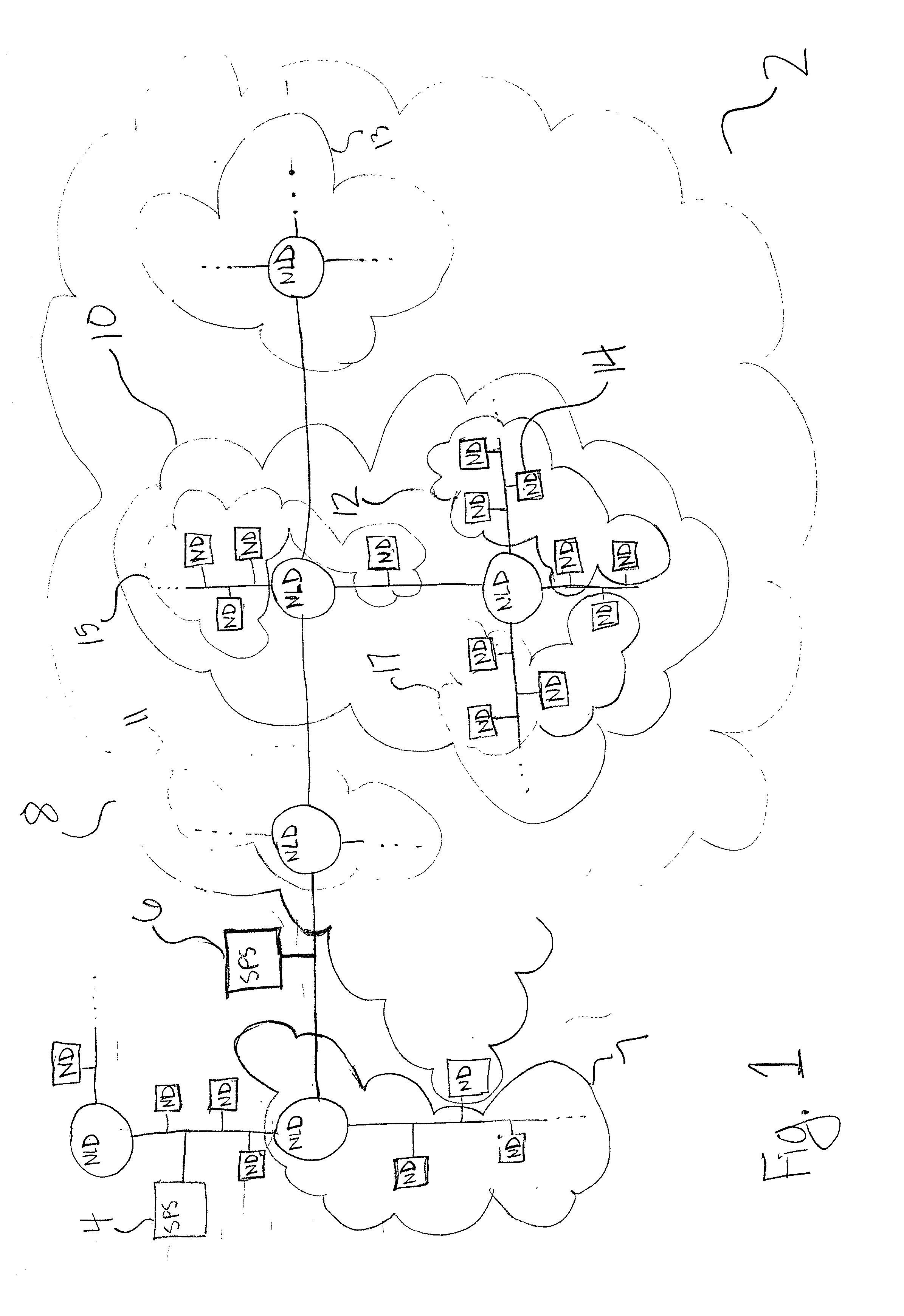
[0049] FIG. 1 is a block diagram illustrating an example of a communications network 2. The communications network 2 comprises a plurality of network devices (NDs) represented as squares, a plurality of network linking devices (NLDs) represented as circles, and a plurality of segments of network transmission media (e.g., wire, cable, optical fiber, transmission waves), which are represented as lines.

[0050] An ND can be any of a plurality of types of network devices including, among other things, any of a variety of computers, for example, a personal computer, a mainframe computer, a workstation, a minicomputer or server, a communication device, for example, a telephony communications device (TCD), a database, or any of a variety of other types of network devices.

[0051] A NLD is a type of ND that is capable of switching, and / or routing packets of data between segments of transmission media. For example, an ND may be a switch, hub, bridge, router, other type of linking device, or a co...


PUM


Abstract

A method of and system for organizing a hierarchy of sets of one or more parameters, for example, configuration parameters, maintaining the plurality of parameter sets, and combining two or more of the plurality of parameter sets to produce a single set of configuration parameters (i.e., an entity profile) for an entity, where such entity may be associated with a communications network. The generated entity profile may be used to configure a device, for example, a network device, associated with the entity. Provided is a digital information product, comprising a computer-readable medium; and first signals tangibly-embodied on the computer-readable medium. The signals define, for an entity associated with a communications network and that belongs to one or more entity groups of a hierarchy of entity groups, a plurality of sets of configuration parameters for configuring a network device of the communications network. Each set corresponds to either the entity or one of the entity groups and, for each set, for one or more configuration parameters, the set defines a value for the configuration parameter. Further provided are a method of and system for assigning values to one or more configuration parameters of a first entity associated with a communications network. The entity is a member of a hierarchy of entity groups, and the communications network comprises a computer-readable medium. A plurality of sets of configuration parameters for configuring a network device of the communications network are retrieved from the computer-readable medium, where each set corresponds to either the entity or one of the entity groups. For each set, for one or more configuration parameters, the set defines a value for the configuration parameter. The plurality of sets of configuration parameters are combined to produce an entity profile for the first entity, where the entity profile comprises one or more configuration parameters and comprises, for each parameter, a corresponding value assigned from one of the plurality of sets of configuration parameters.

Description

RELATED APPLICATIONS[0001] This application claims priority under 35 U.S.C. .sctn. 119(e) to commonly-owned, copending U.S. Provisional Application Serial No. 60 / 190,613, entitled, "Method and Apparatus for Organizing Configuration Information for a Communications System" filed Mar. 20, 2000, which is hereby incorporated by reference in its entirety.[0002] This application is related to commonly-owned, co-pending U.S. patent application entitled "Distributed Communications Network Including One or More Telephony Communication Devices Having Programmable Functionality", by James Batson et al. (hereinafter the Batson application), filed Oct. 26, 2000, which is hereby incorporated by reference in its entirety.BACKGROUND[0003] There are an ever-increasing number of communications networks at use in the world today. Traditionally, communications networks were divided into several types of communications networks that provided particular types of services, including, among other types, te...

Claims


Application Information

Patent Timeline
Patent Type & Authority Applications(United States)
IPC IPC(8): G06F13/00H04L12/24H04L29/06H04L29/08H04M1/247H04M1/253H04M1/57H04M3/42H04Q3/545
CPCH04L29/06027H04L41/0233H04L41/0843H04L41/0846H04L41/0853H04M1/247H04M1/2535H04M1/57H04M3/42H04M3/42068H04M3/4211H04M2203/2044H04Q3/54533H04L67/303H04L67/14H04L69/329H04M1/2471H04L65/1104H04L65/1106H04L65/1101
Inventor SCHAAF, RICHARD W.PETRIE, DANIEL G.
Owner PINGTEL CORP
Learn More