Running method and treatment system for spiral wound membrane element and spiral wound membrane module
Inactive Publication Date: 2002-05-23
NITTO DENKO CORP
View PDF7 Cites 9 Cited by
- Summary
- Abstract
- Description
- Claims
- Application Information
AI Technical Summary
Problems solved by technology
However, the membrane of the hollow fiber membrane element is readily broken, and raw water is disadvantageously mixed into permeate to reduce separation performance when the membrane is broken.
Particularly in dead end filtration, contaminants are so readily deposited on the membrane surface that the water permeation velocity is remarkably reduced and it is difficult to continue stable filtration running.
When the flow rate of the raw water fed in parallel with the membrane surface is increased, however, the recovery per spiral wound membrane element is reduced and a large pump is required for feeding the raw water, while the system cost is remarkably increased.
However, back pressure strength of a separation membrane of a conventional spiral wound membrane element is so low that the separation membrane may be broken when subjected to a back pressure in back wash reverse filtration.
According to an experiment made by the inventor, however, it was difficult to sufficiently remove contaminants when a spiral wound membrane element was subjected to back wash reverse filtration with such a back pressure, and it was impossible to maintain a high permeate flux over a long period.
However, it has not yet been sufficiently verified in relation to a spiral wound membrane element prepared with the separation membrane having such back pressure strength as to the level of a back pressu
Method used
View moreImage
Smart ImageViewing Examples
Examples
 PUM
| Property | Measurement | Unit |
|---|---|---|
| Pressure | aaaaa | aaaaa |
| Pressure | aaaaa | aaaaa |
| Pressure | aaaaa | aaaaa |
Abstract
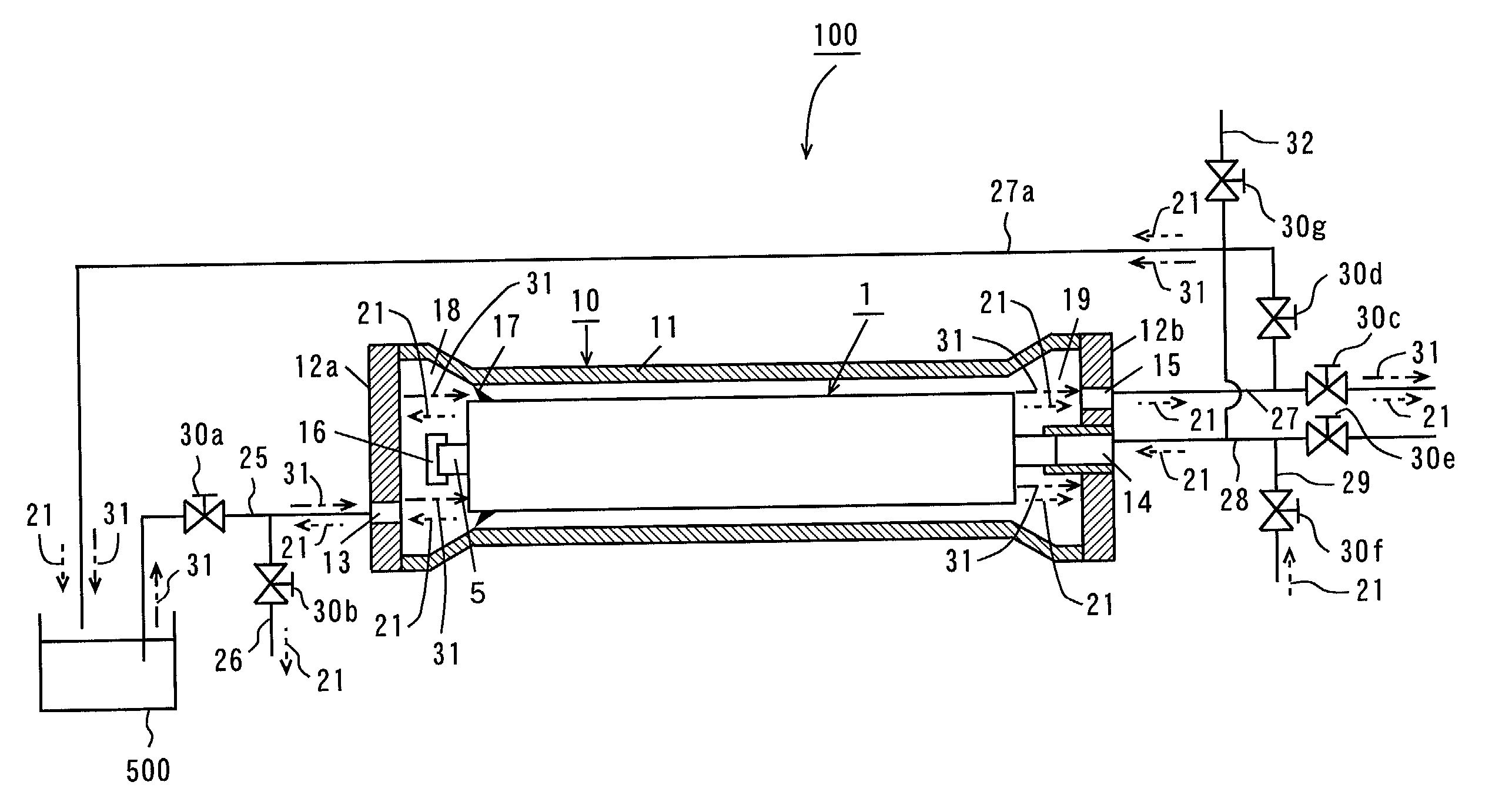
A spiral wound membrane element allowing back wash reverse filtration at 0.05 MPa to 0.3 MPa is employed for a spiral wound membrane module. Air injection of injecting air of not more than 0.3 MPa into a permeate outlet of the spiral wound membrane module from a pressurized air feeder through a pipe, back wash reverse filtration with permeate and flushing with raw water are performed as recovery of a filtration velocity. Another spiral wound membrane module comprises a spiral wound membrane element including a separation membrane having high back pressure strength. Raw water into which bubbles are diffused by an air diffuser is fed to the spiral wound membrane element stored in a pressure vessel. Part of the raw water is axially fed through the spiral wound membrane element, discharged from a raw water outlet of the pressure vessel and thereafter returned to a raw water tank through a pipe.
Description
[0001] 1. Field of the Invention[0002] The present invention relates to a running method and a treatment system for a spiral wound membrane element and a spiral wound membrane module employed for a membrane separator such as a reverse osmosis membrane separator, an ultrafiltration membrane separator, a microfiltration membrane separator or the like.[0003] 2. Description of the Prior Art[0004] Application of membrane separation is recently spread to water purification and waste water treatment, so that membrane separation is applied to hardly treatable liquid quality. In particular, recovery and recycling of industrial waste water through membrane separation is strongly demanded.[0005] A hollow fiber membrane element is generally employed for such membrane separation in consideration of the membrane area (volumetric efficiency) per unit volume. However, the membrane of the hollow fiber membrane element is readily broken, and raw water is disadvantageously mixed into permeate to reduc...
Claims
Login to View More Application Information
Patent Timeline
 IPC IPC(8): B01D61/14B01D61/16B01D63/10B01D63/12B01D63/16B01D65/02B01D65/08B01D67/00B01D69/10B01D71/68C02F1/44
CPCB01D61/145B01D2325/24B01D61/16B01D63/10B01D63/12B01D63/16B01D65/02B01D65/08B01D67/0011B01D69/10B01D71/68B01D2311/04B01D2321/04B01D2321/185B01D2321/2075C02F1/444B01D61/147B01D2311/12B01D2311/14B01D2311/2611B01D67/00113B01D69/1071
Inventor ANDO, MASAAKIISHII, KATSUMIISHIHARA, SATORU
Owner NITTO DENKO CORP
Features
- R&D
- Intellectual Property
- Life Sciences
- Materials
- Tech Scout
- Unparalleled Data Quality
- Higher Quality Content
- 60% Fewer Hallucinations
Learn More Browse by: Latest US Patents, China's latest patents, Technical Efficacy Thesaurus, Application Domain, Technology Topic, Popular Technical Reports.
© 2025 PatSnap. All rights reserved.Legal|Privacy policy|Modern Slavery Act Transparency Statement|Sitemap|About US| Contact US: help@patsnap.com


