Method and apparatus for mandibular osteosynthesis

a mandibular and osteosynthesis technology, applied in the field of surgical applications, can solve the problems of increasing the time of anesthesia and operating room, increasing the potential for infection, and affecting the function of the system, so as to achieve quick and easy contouring of the plate, the effect of increasing strength

Inactive Publication Date: 2002-05-23
BIOMET MICROFIXATION
View PDF10 Cites 103 Cited by
  • Summary
  • Abstract
  • Description
  • Claims
  • Application Information

AI Technical Summary

Benefits of technology

[0012] An advantage of the present invention is the provision of a method and apparatus for mandibular osteosynthesis which quickly and easily contours a plate to the mandible without sacrificing fastener purchase with the bone.
[0014] Another advantage of the present invention is the provision of a method and apparatus for osteosynthesis which incorporates a locking plate with an upwardly curved forward end that more accurately cooperates with the geometry of the human mandible.
[0016] Another advantage of the present invention is the provision of a method and apparatus for mandible osteosynthesis which incorporates a plate reinforcement member which may be selectively secured to a locking plate for increased strength in areas of significant loss of bone mass.

Problems solved by technology

For example, the need for establishing such a secured relationship is often a result of a fracture which has occurred to the bone.
This additional time increases anesthesia requirements and operating room time and also increases the potential for infection.
While known systems utilizing plates and fasteners for cranial and facial osteosynthesis have proven to be acceptable for certain applications, such systems are nevertheless susceptible to improvements that may enhance their performance.
In this regard, many known systems require time consuming surgical attachment.
Additionally, known systems which necessitate the insertion, removal and subsequent reinsertion of fasteners into the bone negatively affect fastener purchase.
Furthermore, many known techniques for cranial facial osteosynthesis disadvantageously position a plate immediately adjacent to the bone which is particularly susceptible to resorption.

Method used


Image

  • Method and apparatus for mandibular osteosynthesis
  • Method and apparatus for mandibular osteosynthesis
  • Method and apparatus for mandibular osteosynthesis

Examples


Embodiment Construction

[0036] The following description of the preferred embodiment of the present invention is merely exemplary in nature and is in no way intended to limit the invention or its application or uses.

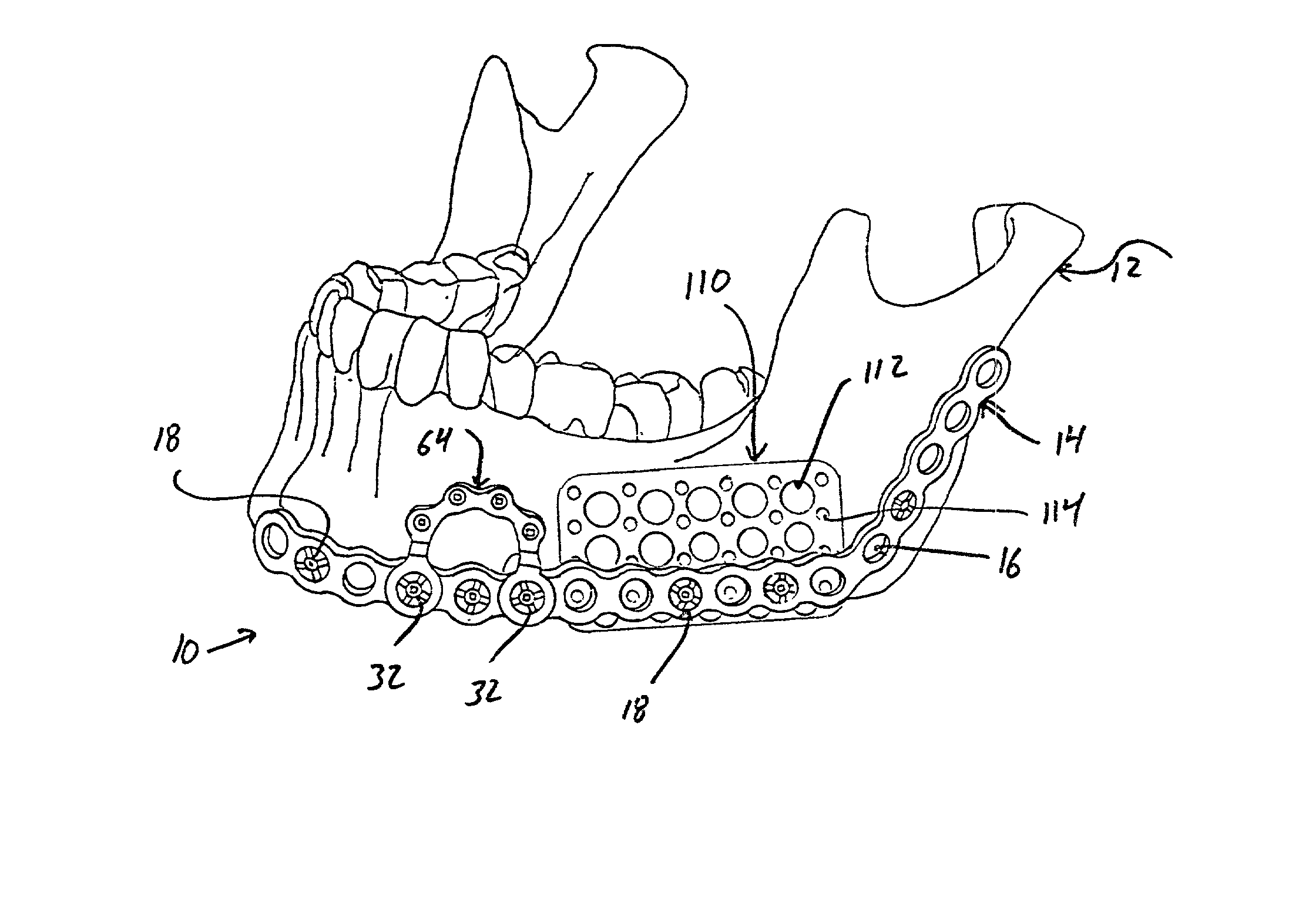
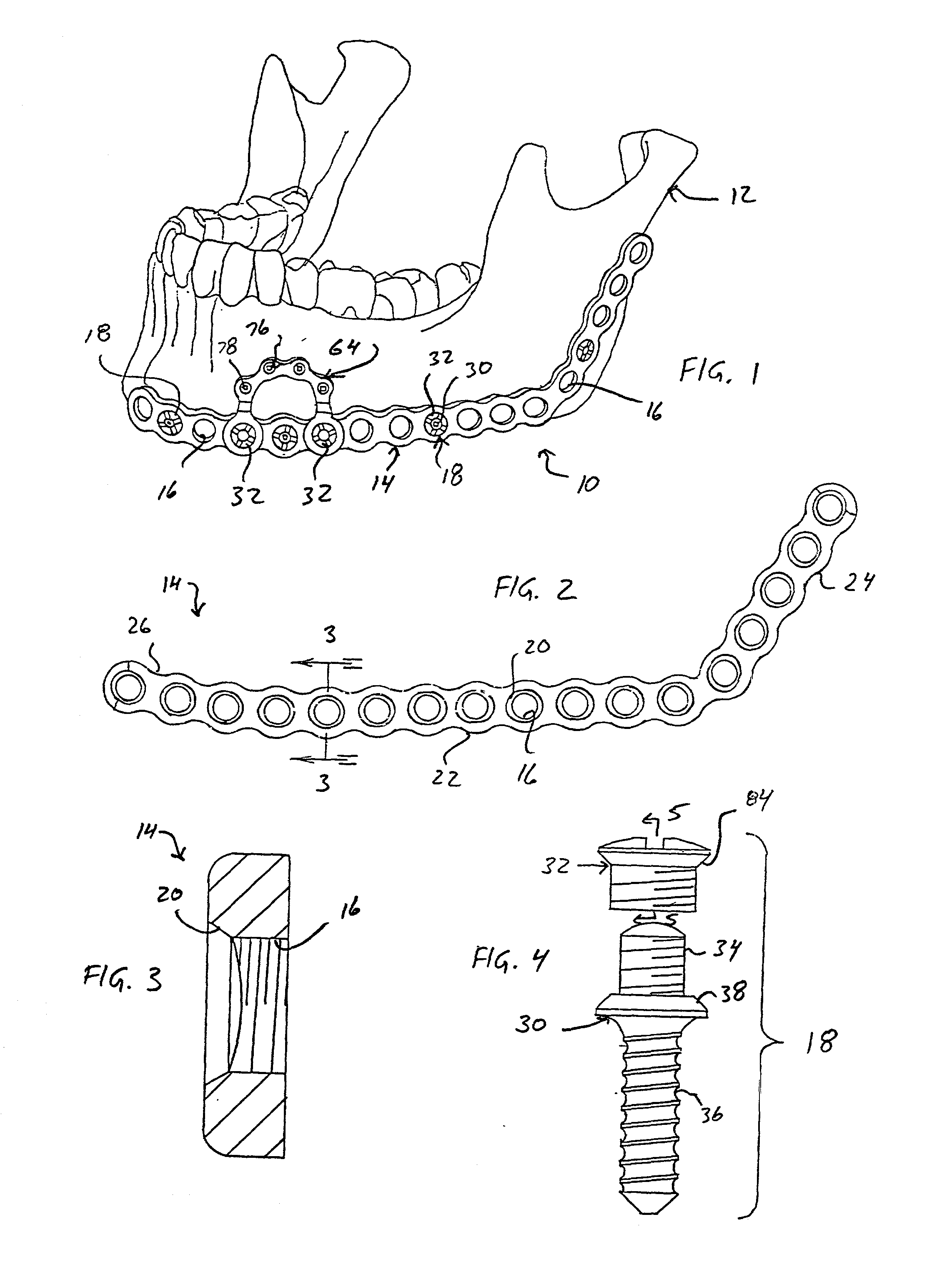
[0037] Referring to FIG. 1, a system constructed in accordance with a preferred embodiment of the present invention is generally identified with reference numeral 10. The system 10 is shown operatively associated with a human mandibular 12. However, it will become apparent to those skilled in the art that certain aspects of the present invention have applicability for other surgical applications.

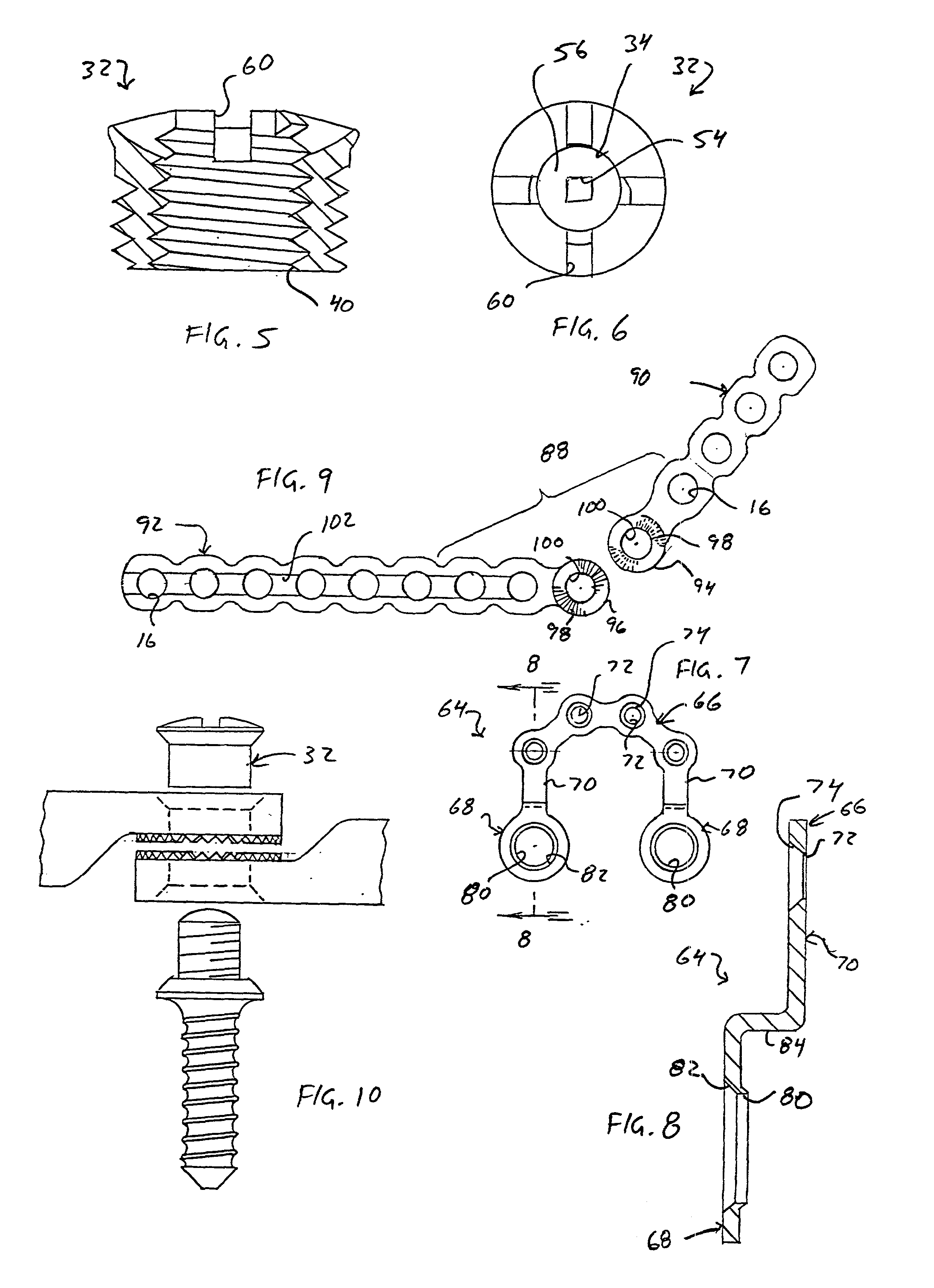
[0038] With continued reference to FIG. 1 and additional references to FIGS. 2 and 3, the system 10 of the present invention is shown to include an elongated reconstruction plate 14. The plate 14 is formed to include a plurality of apertures 16, each adapted to receive a fastener 18 for interconnecting the plate 14 with the mandible 12. The apertures preferably include an oval countersink 20 and are int...


PUM


Abstract

A system for mandibular reconstruction generally includes an elongated locking plate having a plurality of internally threaded apertures and a plurality of fasteners. Each fastener includes a main body portion having an upper threaded shaft and a lower threaded shaft. The lower threaded shaft is adapted to engage the mandible. Each fastener further includes a removable head portion internally threaded for engaging the upper shaft portion and externally threaded for engaging a selected one of the internally threaded apertures of the locking plate. In the preferred embodiment, the thread leads of the head portion and lower shaft of the main body portion are identical. A method of mandibular osteosynthesis utilizes the system of osteosynthesis and generally comprises the steps of temporarily securing the elongated locking plate to the mandible with at least one fastener by engaging the threads of the lower portion with the mandible and threadably engaging the head with the locking plate, unthreading the head portion from the main body of the fastener to thereby allow displacement of the locking plate from the mandible without removing the fasteners from the mandible, performing a surgical procedure (e.g., removal of a cancerous growth), and re-securing the elongated plate to the fastener with the removable head portion.

Description

[0001] This is a continuation-in-part application of U.S. Ser. No. 09 / 025,140, filed Feb. 18, 1998.[0002] 1. Field of the Invention[0003] The present invention relates to surgical applications for the repair of bone fractures and deformities. More particularly, the present invention relates to a method and apparatus for mandibular osteosynthesis.[0004] 2. Discussion of the Related Art[0005] In various orthopedic surgical procedures, it is necessary to align and secure two bone portions in a relatively fixed relationship to each other. For example, the need for establishing such a secured relationship is often a result of a fracture which has occurred to the bone. To ensure that the bone can regenerate in the proper orientation and fuse the fracture, it is important that the bone portions be fixed in the desired position during bone regeneration.[0006] It is known in the art to provide metal plates for the repair of bone fractures. These plates are generally secured to bone portions ...

Claims


Application Information

Patent Timeline
Patent Type & Authority Applications(United States)
IPC IPC(8): A61B17/80A61B17/88
CPCA61B17/8047A61B17/8071Y10S606/904A61B17/888A61B17/8888A61B17/8615
Inventor SCHUMACHER, BRIAN S.STONE, KEVIN T.DUNCAN, JEFFREY A.
Owner BIOMET MICROFIXATION
Why Eureka
Try Eureka