Water conservation system for humidifiers

a technology of water conservation system and humidifier, which is applied in the direction of lighting and heating apparatus, heating types, and separation processes, etc., can solve the problems hot air systems tend to lower the humidity more, and none of the prior art references address the problem of excess water discharge from the humidification system

Inactive Publication Date: 2002-06-13
TRIODYNE WANGLER CONSTR SPECIALTIES
View PDF0 Cites 14 Cited by
  • Summary
  • Abstract
  • Description
  • Claims
  • Application Information

AI Technical Summary

Problems solved by technology

Hot air systems tend to lower the humidity more than other systems due to the evaporation of water particles during heating...

Method used


Image

  • Water conservation system for humidifiers
  • Water conservation system for humidifiers
  • Water conservation system for humidifiers

Examples


Embodiment Construction

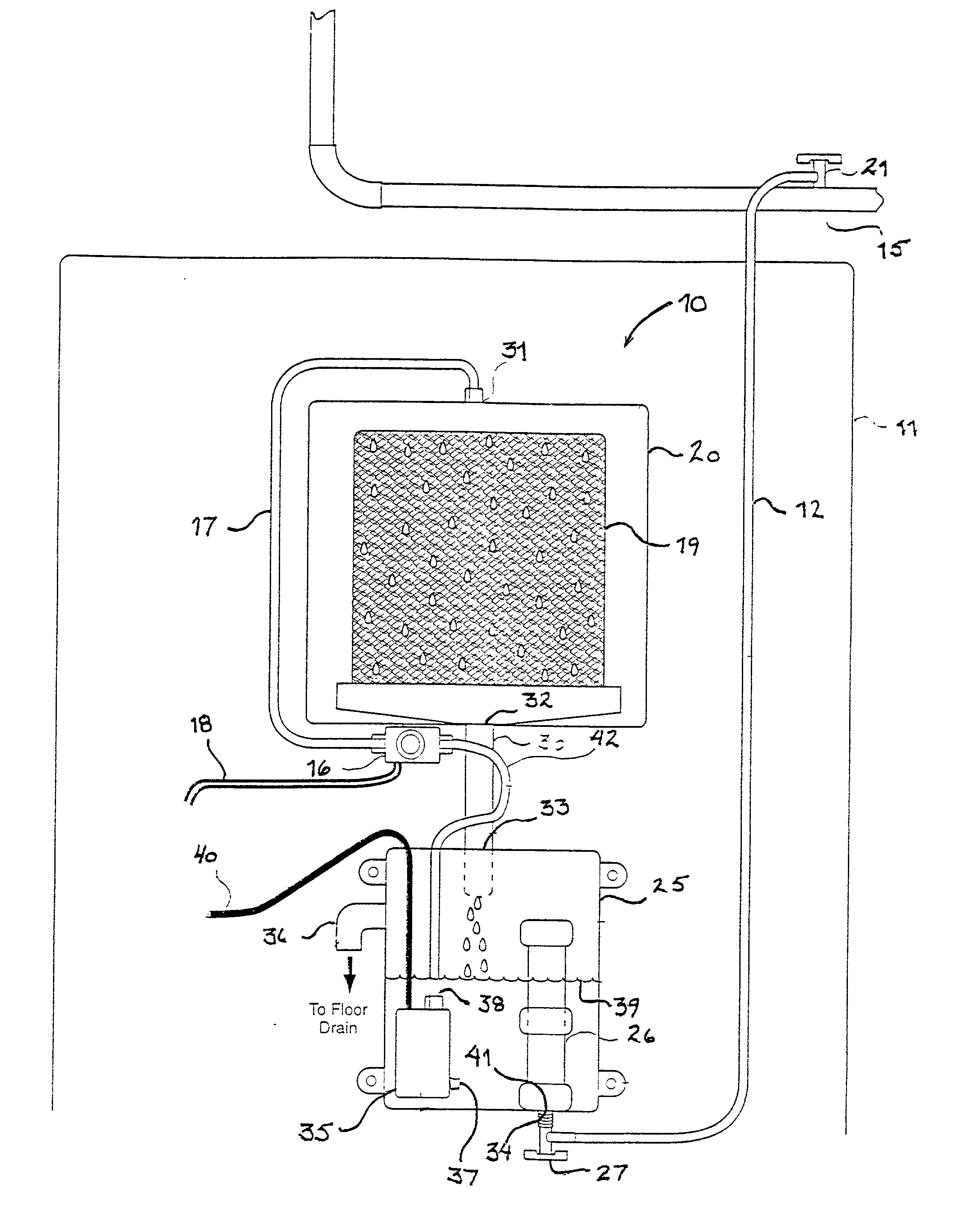
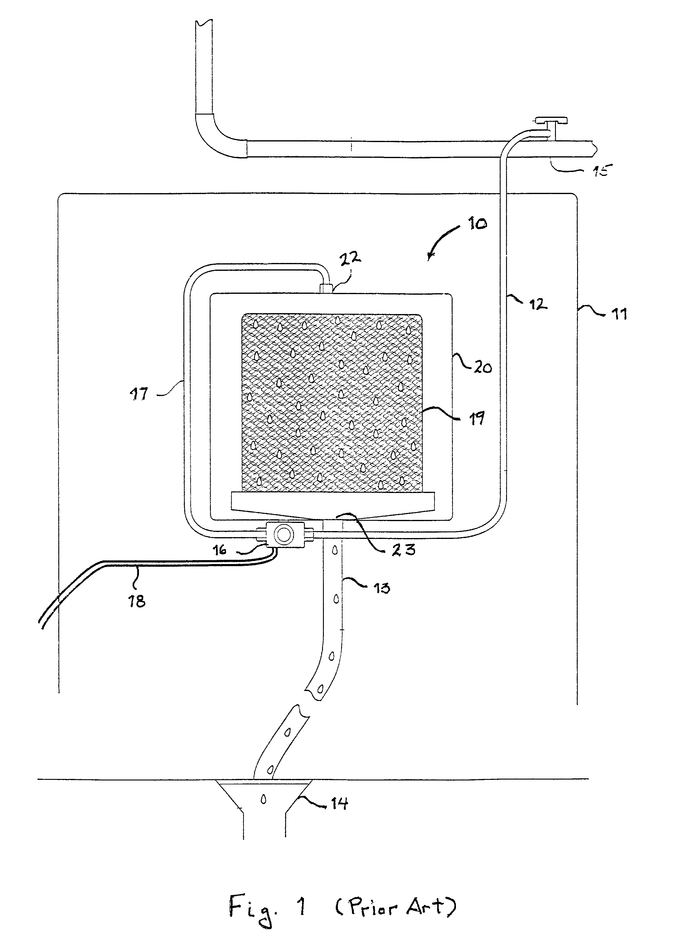
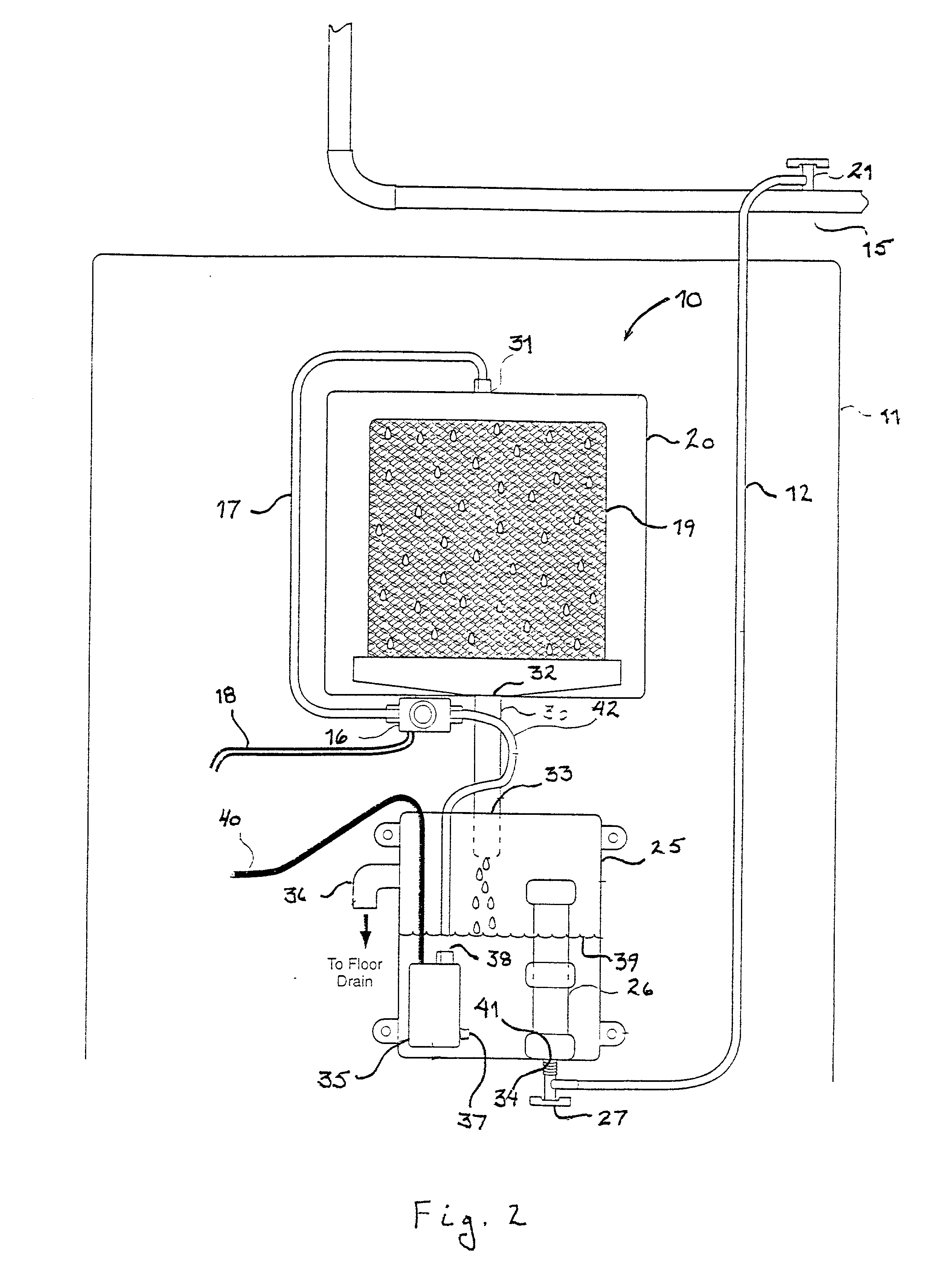
[0015] FIG. 1 shows a conventional humidifier system currently in use and the means for providing humidification to the warm air produced by a residential or building furnace. Humidification system 10 comprises humidifier housing 20 having a water supply inlet 22 and an excess water outlet 23 in fluid communication with excess water drain line 13 which drains excess water into floor drain 14. The humidifier system 10 is typically attached to a wall 11 of the furnace by conventional means whereby the interior space of humidifier housing 20 is in fluid communication with the warm air supply from the furnace. Water is supplied to humidifier system 10 through supply water line 12 which is connected between water supply 15 and the input side of water supply solenoid valve 16. Water supply solenoid valve 16 is operatively connected by means of solenoid valve control line 18 to the furnace control system (not shown) which controls the opening and closing of water supply solenoid valve 16. ...


PUM

PropertyMeasurementUnit
Flow rateaaaaaaaaaa
Levelaaaaaaaaaa

Abstract

A humidification system having a humidifier housing having a supply water inlet and an excess water outlet, which excess water outlet is in fluid communication with a water reservoir vessel. A pump is provided by way of which water in the water reservoir vessel is circulated to the supply water inlet of the humidifier housing.

Description

[0001] 1. Field of the Invention[0002] This invention relates to humidification systems which are of the duct-mounted type, which systems are normally used in ducted forced air heating or air handling systems. More particularly, this invention relates to a humidification system of the duct-mounted type which substantially eliminates the discharge of excess water down the drain.[0003] 2. Description of Prior Art[0004] Humidifiers are commonly used in homes and other types of buildings during the winter to supplement the drop in humidity due to heating systems. Hot air systems tend to lower the humidity more than other systems due to the evaporation of water particles during heating. This, and the fact that hot air furnaces are the easiest to fit with humidifiers, has resulted in a plethora of such devices. Most such devices for hot air systems use a "wetted element". The stationary type of element, such as a sponge, is maintained wet through the use of a constant flow of water. The r...

Claims


Application Information

Patent Timeline
IPC IPC(8): F24F6/04
CPCF24F2006/008F24F6/04
Inventor HARVEL, GERALD STEPHENWANGLER, WILLIAM ANTHONYBARNETT, RALPH LIPSEY
Owner TRIODYNE WANGLER CONSTR SPECIALTIES
Why Eureka
Try Eureka