Strap Wrench

a strap wrench and wrench technology, applied in the field of strap wrenches, can solve the problem of limiting the use of the device, and achieve the effect of enhancing the free movement of the strap

Inactive Publication Date: 2002-07-18
IDEAVILLAGE
View PDF0 Cites 9 Cited by
  • Summary
  • Abstract
  • Description
  • Claims
  • Application Information

AI Technical Summary

Benefits of technology

[0011] It is also a further object of the present invention to create a strap wrench with allows the user to release the strap by simply applying pressure to a rocker arm on the handle of the wrench It is a further object of the invention which allows the user to change the strap when necessary due to wear on the strap or for use with different sized pipes, oil filters, jars and the like.
[0012] It is an additional object of the present invention to creating a strap wrench which reduces the wear on the strap.
[0014] When the strap is drawn through the channel, the strap creates a loop above the top of the handle for placement around the tubular member which requires turning. The strap is initially positioned in the channel by the user pressing one side of the rocker arm to release the open the the channel. Once the strap is initially seated, the rocker arm may be released and the loop may be tightened by pulling the strap through the channel since this will act to move the contact between the strap and the rocker arm to a portion of the rocker arm without a friction means. Once the rocker arm is released, the loop may only be enlarged by applying pressure to one side of the rocker arm. Free movement of the strap may also be enhanced by applying pressure to the rocker arm.

Problems solved by technology

Such a device limits the use of the device when the end of the tubular member is not accessible.

Method used


Image

  • Strap Wrench
  • Strap Wrench
  • Strap Wrench

Examples


Embodiment Construction

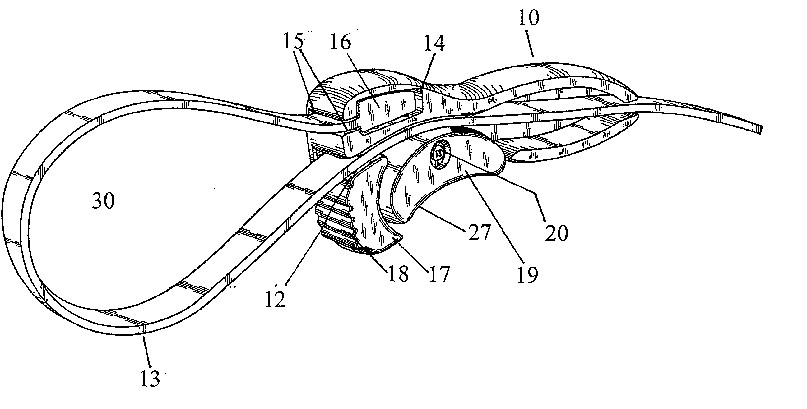
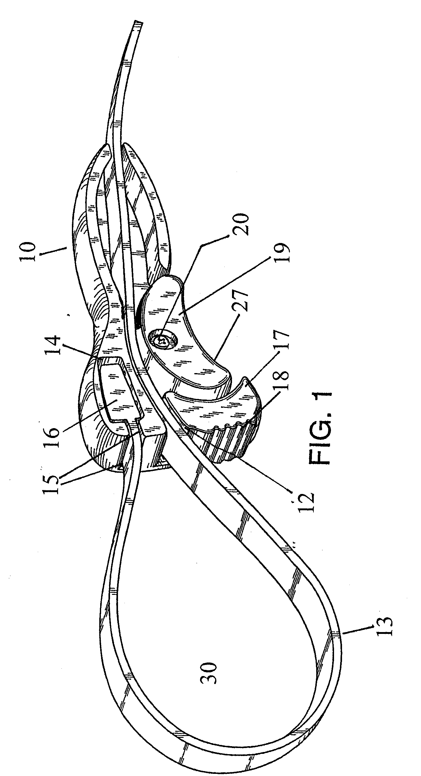
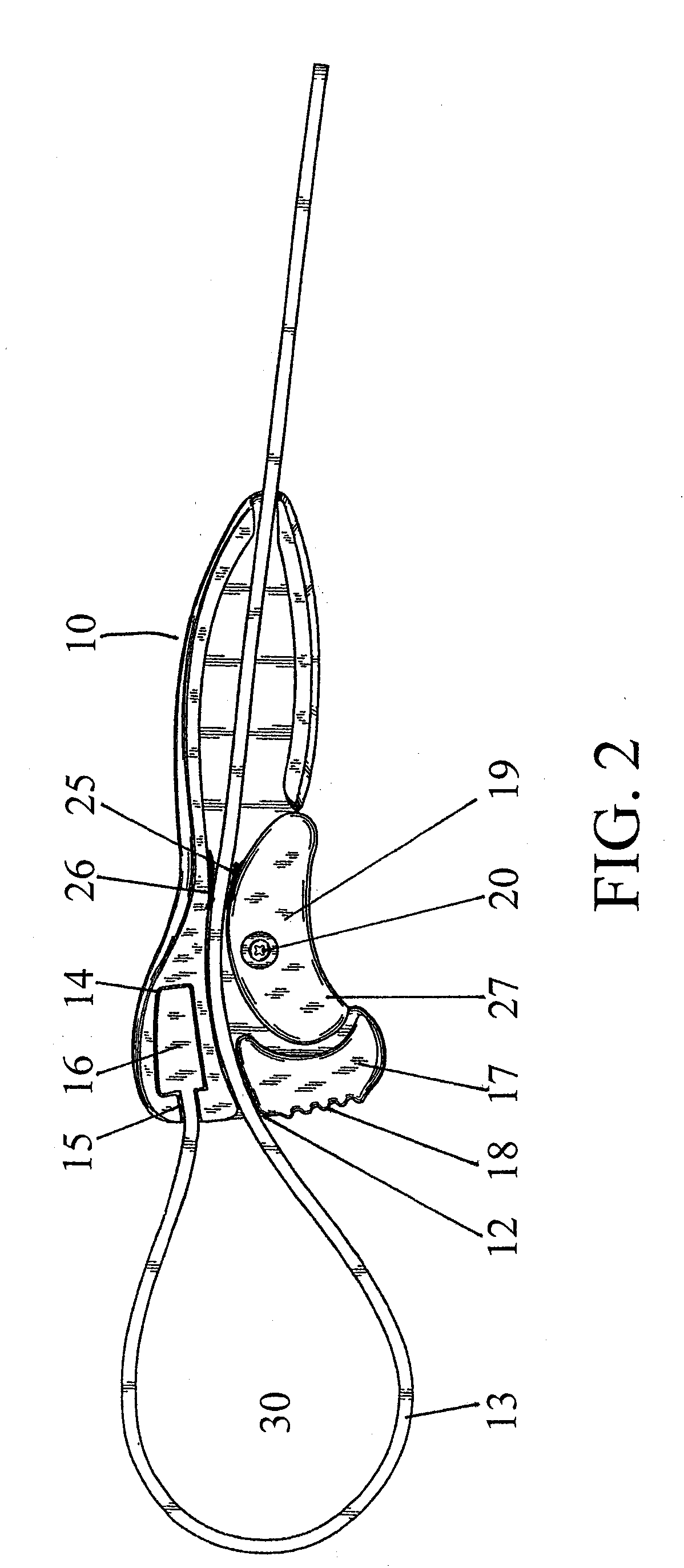
[0022] Referring to Fig. 1 - 6, a driving device in accordance with the present invention is shown for driving tubular members. It comprises a handle 10 having a longitudinal opening or channel 12 passing through its entire length proportioned as to receive a strap 13. In one end of the handle 10 is an enlarged cavity 14 in communication with a slit 15. Slit 15 forms an open passage between the enlarged cavity 14 and the exterior of the handle 10. Strap 13 has an enlarged end 16 positioned within cavity 14. The portion of strap 13 adjacent the enlarged end 16 passes through slit 15. This arrangement anchors the enlarged end 16 of strap 13 in the handle 10, but allows replacement of the strap to replace a worn strap or to use straps at different length.

[0023] In use the other end of strap 13 passes through channel 12 in the handle 10, thereby forming a loop 30 for engaging a tubular member (not shown) which is to be driven by the strap wrench. The handle 10 both holds the strap13 in ...


PUM


Abstract

<heading lvl="0">Abstract of Disclosure< / heading> A strap wrench comprising a handle with a central channel and detachable strap anchored at one end of the handle. The strap is held in place in a channel by means of a rocker arm which is biased to press the strap against a portion the strap positioned in the channel. The strap is initially positioned in the channel by the user pressing one side of the rocker arm to open the channel. Once the strap is initially seated, the rocker arm may be released and the loop may be further tightened by pulling the strap through the channel. Free movement of the strap may be enhanced by applying pressure to the rocker arm.

Description

Background of Invention[0001] Field of the invention[0002] The invention relates to driving devices for use with tubular members and more particularly to an improved strap wrench.[0003] Description of the Prior Art[0004] Strap wrenches have been in existence for over 100 years to drive tubular members. Strap wrenches use a flexible strap positioned and tightened around the tubular member to transmit a turning force to the tubular member. These devices usually consist of a strap loop anchored at one end to a handle. Its other end is connected to a clamping means on or in the handle to draw the strap tightly around the tubular member to allow the application of torque through the strap to the tubular member.[0005] Strap wrenches may be used for many different applications. Since engine oil filters are of such a large diameter that they can not be turned with most traditional wrenches, a strap wrench is the ideal tool for removing and replacing the filter. Equally, water and gas pipes ...

Claims


Application Information

Patent Timeline
Patent Type & Authority Applications(United States)
IPC IPC(8): B25B13/52
CPCB25B13/52
Inventor KHUBANI , ANAND V.
Owner IDEAVILLAGE
Why Eureka
Try Eureka