
Electrical remote-control and remote-power flying saucer

a technology of electric remote control and flying saucer, which is applied in the direction of automatic actuation, aircraft navigation control, vertical landing/take-off, etc., can solve the problems of inability to control the aircraft attitude, inability to perform stationary flight, and lack of on-board batteries with a sufficient power-to-weight ratio to provid

Inactive Publication Date: 2002-08-08
LOUVEL PHILIPPE
View PDF0 Cites 119 Cited by
  • Summary
  • Abstract
  • Description
  • Claims
  • Application Information

AI Technical Summary

Benefits of technology

[0129] One of the advantage of the invention is to propose an aircraft system which is enjoyable and educative, particularly suitable for the training to control an helicopter-like aircraft.[0130] Another advantage of the invention is to propose, with an on-board micro video camera, a very useful system of remote inspection.[0131] EXEMPLE OF DIMENSIONS FOR THE TOY VERSION[0132] Propeller diameter: 15 to 20 cm[0133] aircraft diameter: 50 cm[0134] aircraft weight 400 g[0135] Voltage: 14 V[0136] Rechargeable battery capacity: 1,5 A.h

Problems solved by technology

The drawback of this invention is that the control of the aircraft attitude is not possible by adjusting only the speed of the motor, as supposed in the patent description.
But this arrangement is not able to perform stationary flight.
The drawback of this invention is that according to the current technical state of the art, it does not exist any on-board battery with a sufficient power-to-weight ratio to provide enough thrust for stationary flight.
The drawback of this arrangement is that the rotatable electric switch is rather complex to manufacture and the response time of the electric motors must be very efficient, thus increasing the cost of such an aircraft.

Method used


Image

  • Electrical remote-control and remote-power flying saucer
  • Electrical remote-control and remote-power flying saucer
  • Electrical remote-control and remote-power flying saucer

Examples


Embodiment Construction

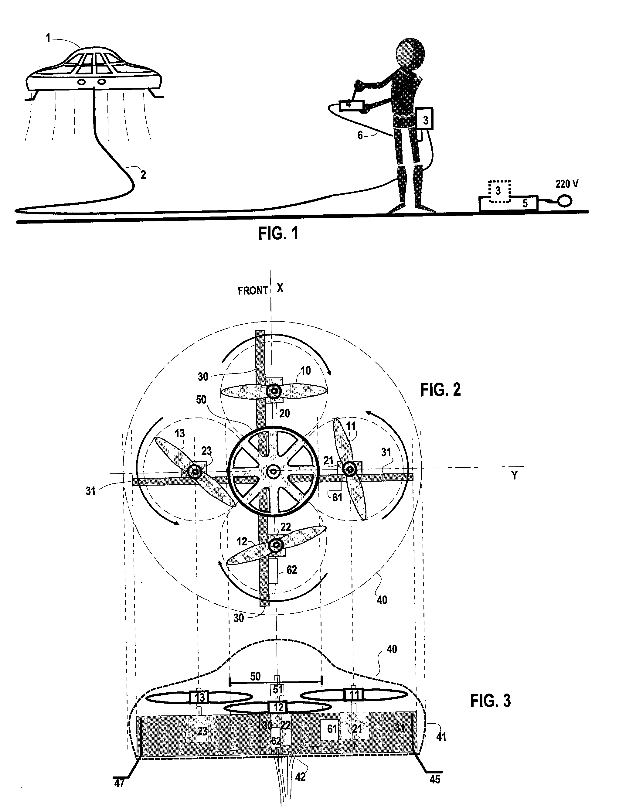
[0025] The aircraft (1) has a general shape looking like a flying saucer, as shown in FIG. 1. It is linked to the control unit (3) by a multi-wire flexible cable (2).

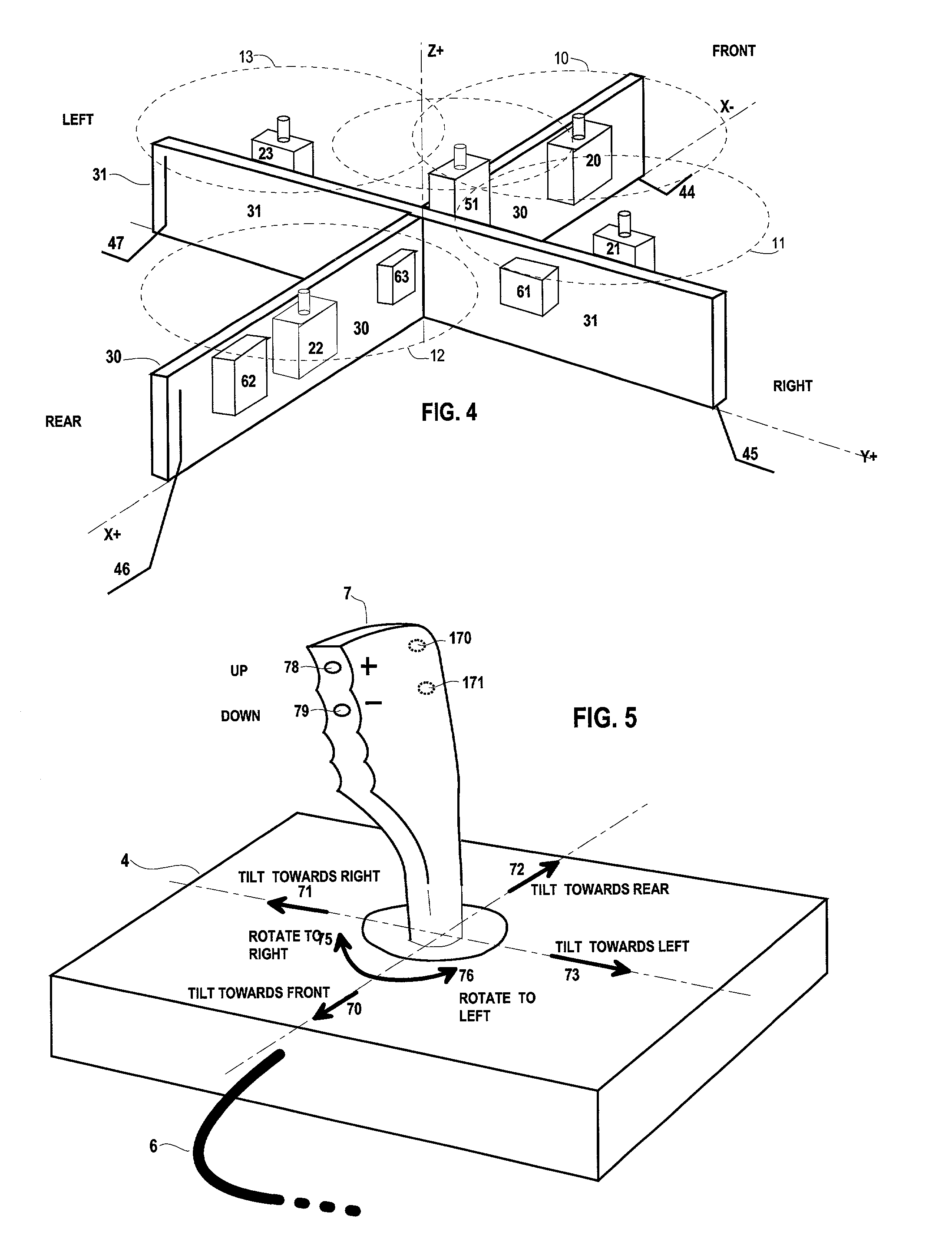
[0026] The handling unit (4) is handled by the user and is linked to the control unit (3) by a multi-wire flexible cable (6).

[0027] The control unit (3) is either carried by the user or either may be plugged into a loading base (5) that is connected to the mains.

[0028] AIRCRAFT (1)

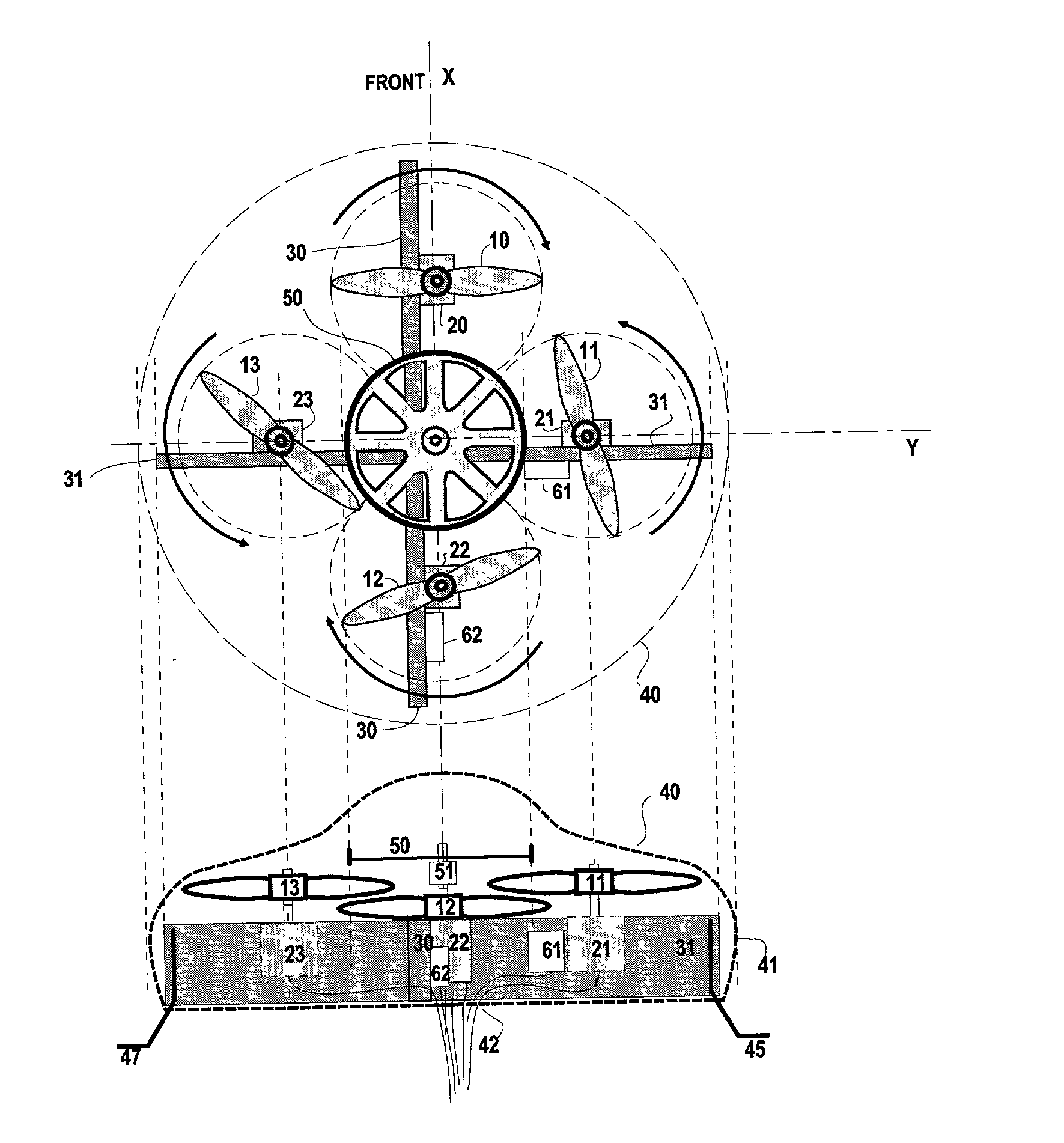
[0029] As shown in drawings FIG. 2 and FIG. 3, the aircraft includes four propellers (10), (11), (12), (13) with vertical axis, that provides the lift thrust. The propellers are arranged in a square pattern, in a horizontal plan.

[0030] Each propeller is driven independently by an electric motor. The propeller (10) is driven by the motor (20). The propeller (11) is driven by the motor (21). The propeller (12) is driven by the motor (22). The propeller (13) is driven by the motor (23).

[0031] The frame that bears the motors is made of two rectang...


PUM


Abstract

The purpose of the invention is a light aircraft, remotely supplied and remotely controlled, propelled by electrical motors coupled to propellers, this device being able to perform stationary flight and to move in the three space dimensions in a controlled way. The system includes an aircraft (1), a control unit (3) and a handling unit (4). The aircraft comprises four propellers, each of them driven by a electric motor, a gyroscopic device, tilt sensors, a yaw sensor and an extrenal protective body. The invention also describes the method for the fliht closed loop control. The main purpose of this invention is to provide a enjoyable and educative toy, mainly intended for indoor flight. In a variant of the invention, the aircraft is fitted with a miniaturized video camera, in order to perform remote inspections on buildings or elements difficult to access.

Description

[0001] The present invention relates to a light aircraft, like a flying saucer, remotely controlled and remotely powered, able to perform stationary flight and to move in the three directions.PRIOR ART[0002] U.S. Pat. No. 4,161,843, issued in 1979, is known. It discloses a toy aircraft fitted with four propellers driven by a single electric motor, remotely powered. The drawback of this invention is that the control of the aircraft attitude is not possible by adjusting only the speed of the motor, as supposed in the patent description.[0003] Patent FR2737130, issued in 1997, is known. It presents a light plane with a propeller driven by an electric motor, remotely controlled and remotely powered, intended for indoor flight. But this arrangement is not able to perform stationary flight.[0004] U.S. Pat. No. 5,672,086, issued in 1997 is known. It presents an aircraft with two propellers, powered by an on-board electrical power source, remotely and wirelessly controlled. The drawback of ...

Claims


Application Information

Patent Timeline
Patent Type & Authority Applications(United States)
IPC IPC(8): A63H27/00A63H27/04A63H27/127A63H30/02B64C13/20B64C15/00B64C27/08B64C29/02G05D1/10
CPCA63H27/002A63H27/04A63H27/12A63H30/02
Inventor LOUVEL, PHILIPPE
Owner LOUVEL PHILIPPE
Learn More