Emission control apparatus

Inactive Publication Date: 2002-08-08
CLEAN AIR POWER
6 Cites 23 Cited by

AI-Extracted Technical Summary

Problems solved by technology

Such designs resulted in increased pressure drop, required frequent replacement of catalyst and required inspiration of atmospheric air to aid in oxidation of carbon monoxide and unburned hydrocarbons.
This would result in directing untreated, polluted exhaust gases to the atmosphere.
Problems associated with three-way catalytic converters have been identified as: imprecise air/fuel ratio control, deactivation of the catalyst and flow maldistribution at the front area of the catalytic converter.
As previously stated, one of the primary problems to consider in a combined catalytic converter and exhaust silencer, particularly for efficiency of catalytic conversio...

Method used

[0028] One or more additional tubular members are disposed near outer walls of the housing 1 extending through the second and third chambers 11 and 12, providing for flow of exhaust gases, of less noxious components, from the first chamber 10 into the fourth chamber 13 for eventual discharge through the outlet 5. In the exemplary embodiment there are four such tubular members 20, 21, 22 and 23. The ends of the additional tubular members are open and the walls thereof may be perforated, as shown at 24, 25, 26 and 27 for reduction of noise as the less noxious exhaust gas compounds flow therethrough for eventual discharge through the outlet 5. Actually, the diameter and length of the tubular members 6, 20, 21, 22, 23 and the size and number of perforations ...

Benefits of technology

0018] The present invention provides apparatus for controlling emissions from an internal combustion engine to reduce noxious gas emissions and to reduce noise therefrom. The apparatus may include an enclosed housing having an inlet at one end t...

Abstract

Apparatus for controlling emissions from an internal combustion engine including an enclosed housing one end of which is provided with an inlet and the other end an outlet. A coaxial tubular member extends from the inlet into the housing. A catalytic cell surrounds the tubular member and separates two chambers, a first surrounding the tubular member near the inlet and the other on the opposite side of the catalytic cell. Exhaust gases from the internal combustion engine flow through the tubular member, expanding into the other chamber, then through the catalytic cell for conversion of nitrogen oxides, carbon monoxide and unburned hydrocarbons to less noxious components, expanding into the first chamber for eventual discharge through the outlet.

Application Domain

Technology Topic

Image

  • Emission control apparatus

Examples

  • Experimental program(1)

Example

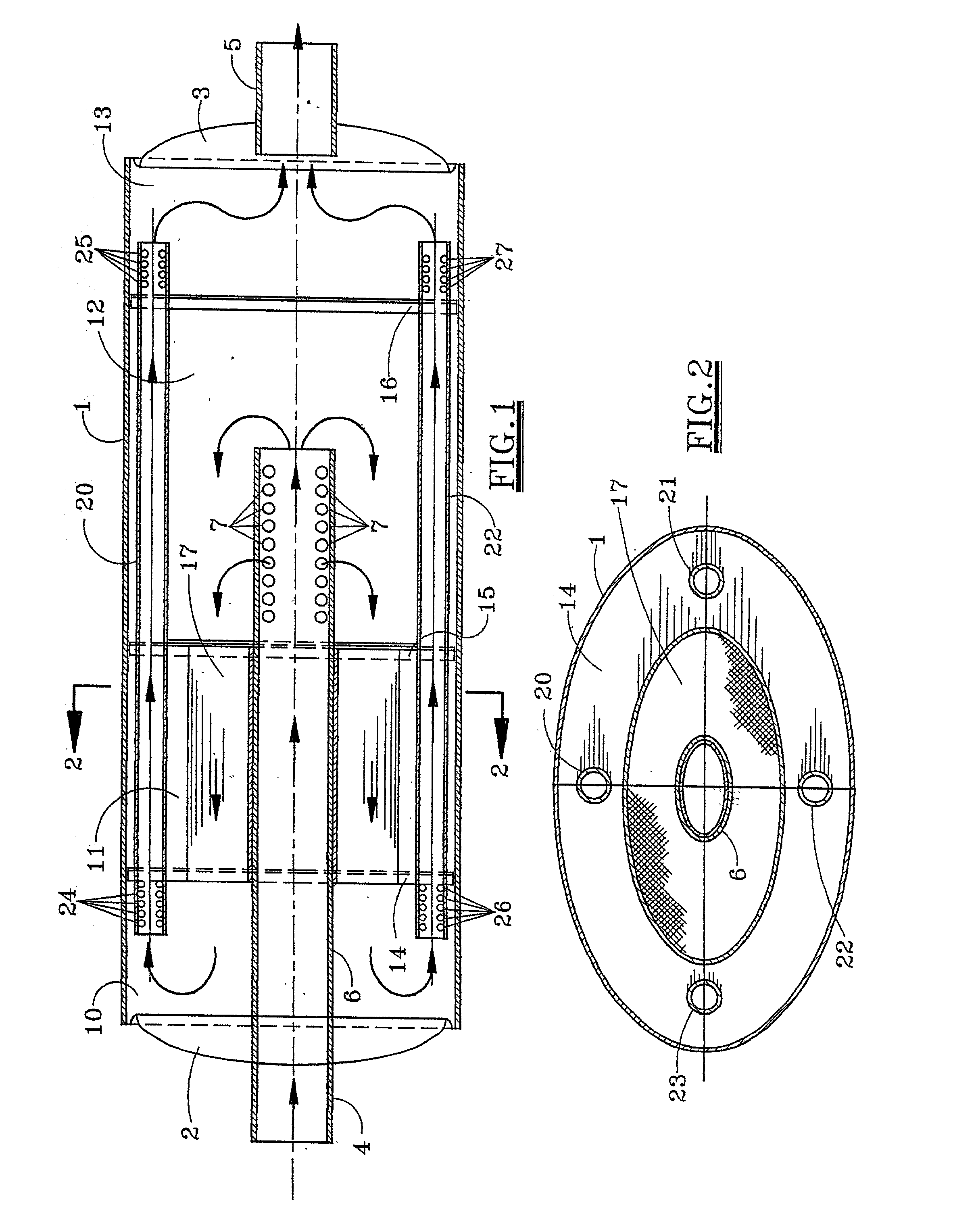
[0026] Referring first to FIGS. 1 and 2, there is shown an apparatus for controlling emissions from an internal combustion engine. The apparatus is a combination noise and pollution control apparatus, particularly adapted for use with an automobile. It includes a cylindrical housing 1 closed at opposite ends by dished heads 2 and 3. The housing 1 can be cylindrical or, as in the preferred embodiment illustrated in FIGS. 1 and 2, of elliptical cross-section. If cylindrical, the heads 2 and 3 are semi-spherical. If elliptical, they are semi-elliptical in shape. The head 2 is provided with a single inlet 4 by which the apparatus may be connected to the exhaust (not shown) of an internal combustion engine (not shown). The opposite head 3 is provided with an outlet 5. The outlet 5 may be connected to a discharge pipe (not shown) or in the case of an automobile to the tailpipe (not shown). In the exemplary embodiment, the inlet 4 is formed by the end of a tubular member 6 which is coaxially disposed in the housing 1 and extends, uninterrupted, from the inlet well into the housing 1. The end of the tubular member opposite the inlet 4 is open and the walls thereof are perforated 7 allowing exhaust gases to enter or exit the tubular member therethrough.
[0027] In the preferred embodiment, the housing 1 is divided from one end toward the other into first, second, third and fourth chambers, 10, 11, 12 and 13, respectively, by first, second and third partitions or baffles 14, 15, 16, respectively. The first partition 14 may actually be a baffle with perforations or passages through the walls thereof. Partitions 15 and 16 are not perforated and seal chambers 12 and 13 from other chambers. A honeycomb type catalytic cell 17 surrounds the tubular member 6. The honeycomb catalytic cell is formed by depositing a suitable catalytic formulation on a ceramic or metallic substrate. In a preferred embodiment, the catalytic formulation is a three-way catalyst of platinum, palladium and rhodium. Gases, totally confined within tubular member 6 until entering the third chamber 12, expand and flow through the catalytic cell 17 into another expansion chamber, the first chamber 10. As the exhaust gases from the internal combustion engine flow through the catalytic cell, nitrogen oxides, carbon monoxide and unburned hydrocarbons are converted to less noxious components, without induction of additional air or oxygen as in prior designs. The catalytic cell 17 is annular in cross section. Actually, in the preferred embodiment shown in FIGS. 1 and 2, the tubular member 6 is of elliptical cross-section and the catalytic cell is of coaxial elliptical annular cross-section.
[0028] One or more additional tubular members are disposed near outer walls of the housing 1 extending through the second and third chambers 11 and 12, providing for flow of exhaust gases, of less noxious components, from the first chamber 10 into the fourth chamber 13 for eventual discharge through the outlet 5. In the exemplary embodiment there are four such tubular members 20, 21, 22 and 23. The ends of the additional tubular members are open and the walls thereof may be perforated, as shown at 24, 25, 26 and 27 for reduction of noise as the less noxious exhaust gas compounds flow therethrough for eventual discharge through the outlet 5. Actually, the diameter and length of the tubular members 6, 20, 21, 22, 23 and the size and number of perforations 7, 24, 25, 26, 27 provided therein are selected to provide optimum noise reduction and uniform flow distribution of exhaust gases through the apparatus.
[0029] In operation, exhaust gases from an internal combustion engine flow uninterrupted through the inlet 4 and the tubular member 6 into the expansion or third chamber 12. Flow is then reversed as indicated by the arrows therein so that the exhaust gases spread out and then flow through the catalytic module or cell 17 into the first chamber 10. As the exhaust gases flow through the catalytic module 17, nitrogen oxides, carbon monoxide and unburned hydrocarbons are converted (three-way catalyst) to less noxious compounds without addition of air or oxygen as in prior art two-way catalyst designs.
[0030] From the first chamber 10, the exhaust gases, now of less noxious compounds, flow through the tubular members 20, 21, 22, 23 into the fourth chamber 13 and are eventually discharged through outlet 5 to the atmosphere or for further handling. The arrows in FIG. 1 indicate the travel of the exhaust gases from the inlet 4 to the outlet 5.
[0031] As the exhaust gases flow from the tubular member 6 into the chamber 12, they flow out the end of the tubular member 6 and through the perforations 7 spreading out for more even distribution and flow at reduced velocities through the catalyst or catalytic cell 17. The particular arrangement, in which the catalytic cell 17 is of annular or semi-elliptical annular cross-section, also results in more even distribution and flow at reduced velocities, resulting in increased converter residence time, increased life of catalyst and greater efficiency in reducing noxious exhaust gases to less noxious gases.
[0032] The emission control apparatus of the present invention also provides, in unique combination, noise reduction components. In its elliptical cross-sectional construction as illustrated in FIGS. 1 and 2, the apparatus is particularly adapted for use for catalytic conversion and noise reduction for an automobile. The apparatus is relatively simple in construction and operation. Most importantly, it is extremely efficient and cost effective in reducing noise and air pollution from internal combustion engines.
[0033] Two embodiments of the invention have been described herein, one of cylindrical cross-section and another of elliptical cross-section. However, many variations of the invention will be apparent to those skilled in the art. Accordingly, it is intended that the scope of the invention be limited only by the claims which follow.

PUM

PropertyMeasurementUnit
Flow rate
Diameter
tensileMPa
Particle sizePa
strength10

Description & Claims & Application Information

We can also present the details of the Description, Claims and Application information to help users get a comprehensive understanding of the technical details of the patent, such as background art, summary of invention, brief description of drawings, description of embodiments, and other original content. On the other hand, users can also determine the specific scope of protection of the technology through the list of claims; as well as understand the changes in the life cycle of the technology with the presentation of the patent timeline. Login to view more.

Similar technology patents

Rapid pressure relief extraction method for short drill hole of fully mechanized coal mining face

ActiveCN114198141AReduce gas emissionReduce ventilation pressureDrilling rodsConstructionsCoal miningDrill hole
Owner:中煤昔阳能源有限责任公司白羊岭煤矿

Gas turbine engine and control method

Owner:SIEMENS ENERGY GLOBAL GMBH & CO KG

Regenerated sealing oil composition and gas holder using same

InactiveCN103266003AHigh viscosityReduce gas emissionVariable capacity gas holdersLubricant compositionPistonFuel tank
Owner:SHOUGANG JINGTANG IRON & STEEL CO LTD

Classification and recommendation of technical efficacy words

  • Reduce noise
  • Reduce gas emission

Regenerated sealing oil composition and gas holder using same

InactiveCN103266003AHigh viscosityReduce gas emissionVariable capacity gas holdersLubricant compositionPistonFuel tank
Owner:SHOUGANG JINGTANG IRON & STEEL CO LTD

Rapid pressure relief extraction method for short drill hole of fully mechanized coal mining face

ActiveCN114198141AReduce gas emissionReduce ventilation pressureDrilling rodsConstructionsCoal miningDrill hole
Owner:中煤昔阳能源有限责任公司白羊岭煤矿

Gas turbine engine and control method

Owner:SIEMENS ENERGY GLOBAL GMBH & CO KG
Why Eureka
Try Eureka