Gas turbine engine and control method

Active Publication Date: 2020-09-17
SIEMENS ENERGY GLOBAL GMBH & CO KG
View PDF0 Cites 0 Cited by
  • Summary
  • Abstract
  • Description
  • Claims
  • Application Information

AI Technical Summary

Benefits of technology

[0004]The present invention seeks to solve the problem of reducing emissions of gas turbine engines and particularly when operating across the full range of operating power outputs. Another problem solved by the present invention is to maintain constant temperatures of the combustor so that emission

Problems solved by technology

Another problem being solved is to improve combustion stability and therefore improve operability of the gas turbine engine.
Another problem b

Method used


Image

  • Gas turbine engine and control method
  • Gas turbine engine and control method
  • Gas turbine engine and control method

Examples


Example

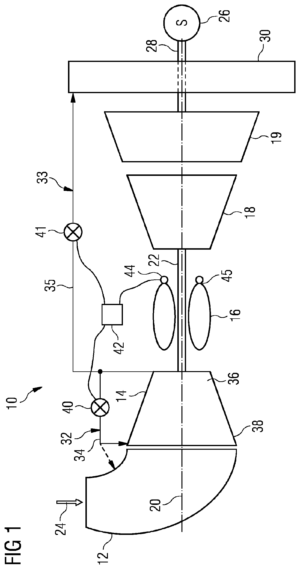
[0028]FIG. 1 shows an example of a gas turbine engine 10 in a sectional view. The gas turbine engine 10 comprises, in flow series, an inlet 12, a compressor 14, a combustor 16 and a turbine 18 which are generally arranged in flow series and generally about and in the direction of a longitudinal or rotational axis 20. The gas turbine engine 10 further comprises a first shaft 22 which is rotatable about the rotational axis 20 and which extends longitudinally through part of the gas turbine engine 10. The first shaft 22 drivingly connects the turbine 18 to the compressor 14. The turbine 18 is sometimes known as the compressor-turbine or high-pressure turbine. A power turbine 19 may be located downstream of the compressor-turbine 18. The power turbine 19 may be drivingly connected to a load 26 via a second shaft 28. Alternatively the compressor turbine 18 may be drivingly connected to the load 26 via a shaft. An exhaust 30 is located downstream of the compressor-turbine 18 and downstrea...


PUM


Abstract

A method of controlling a gas turbine engine capable of operating in at least a high, medium-high, medium, medium-low, and low output power ranges. The method includes during the medium-high output power range varying the angle of the variable guide vanes so that a third predetermined temperature of the combustor is maintained, during the medium output power range the variable guide vanes are closed and bleeding a gas from a downstream part of the compressor to an upstream part of the compressor so that a first predetermined temperature of the combustor is maintained, during the medium-low output power range the variable guide vanes are closed and bleeding a gas from a downstream part of the compressor to an upstream part of the compressor and bleeding a gas from the downstream part of the compressor to the exhaust so that a second predetermined temperature of the combustor is maintained.

Description

CROSS REFERENCE TO RELATED APPLICATIONS[0001]This application is the US National Stage of International Application No. PCT / EP2018 / 078973 filed 23 Oct. 2018, and claims the benefit thereof. The International Application claims the benefit of European Application No. EP17199218 filed 30 Oct. 2017. All of the applications are incorporated by reference herein in their entirety.FIELD OF THE INVENTION[0002]The present invention relates to a method of controlling a gas turbine and a gas turbine engine and in particular but not exclusively a method of controlling a gas turbine comprising operating variable guide vanes and compressor bleeds to maintain more constant combustion temperature, for reduced emissions, at different demanded loads and a gas turbine engine having a compressor with variable guide vanes and a number of bleed systems. The gas turbine engine is advantageously a single-shaft engine, but may be a two or three shaft engine.BACKGROUND[0003]For a single shaft gas turbine, wh...

Claims


Application Information

Patent Timeline
IPC IPC(8): F02C9/22F02C9/18F02C9/28
CPCF05D2240/12F02C9/22F02C9/18F02C9/28F05D2270/303F05D2270/05F05D2260/606F05D2270/08F02C9/20
Inventor BULAT, DIANASKIPPER, DORIANSMITH, MICHAEL
Owner SIEMENS ENERGY GLOBAL GMBH & CO KG
Why Eureka
Try Eureka