

Sleeve bearing arrangement
a technology of sleeve bearings and bearings, which is applied in the direction of bearing components, shafts and bearings, mechanical equipment, etc., can solve the problems of both merits and demerits of the method of lengthening the service life of the sleeve bearings, and the room left for improvement, so as to achieve low cost, light weight, and slow rotation speed
Inactive Publication Date: 2002-08-22
MINEBEAMITSUMI INC
View PDF0 Cites 26 Cited by
- Summary
- Abstract
- Description
- Claims
- Application Information
AI Technical Summary
Benefits of technology
[0004] In the past, sleeve bearings made of resin such as polyacetal, polyamide, etc. have been in use for rotating parts which are light in weight and slow in rotation speed because such sleeve bearings are available at a low cost in comparison with sleeve bearings made of metal.
[0005] However, as a lubricating oil is required between a shaft and a sleeve bearing, a method of lengthening a service life of the sleeve bearing has been under study. There are available various methods such as a method of increasing an mount of oil by increasing a volume of a shaft impregnated with oil, a method of replenishing oil by providing an oil pan, a method of preventing spilling of oil by devising an oil seal, and so forth. However, any of these methods has both merits and demerits, and there is room left for improvement.
[0007] Further, it has been found that the CRB ceramics described above are insusceptible to damage, light in weight, and has a long service life, having in addition ability to retain oil and grease for a long period of time. It has also been found that the porous material has not only the ideal characteristics as the material suitable for use in the sleeve bearings but also a small contraction ratio of the dimensions of a formed workpiece formed thereof to those of a finished product.
Problems solved by technology
However, as a lubricating oil is required between a shaft and a sleeve bearing, a method of lengthening a service life of the sleeve bearing has been under study.
However, any of these methods has both merits and demerits, and there is room left for improvement.
Further, it has been found that the CRB ceramics described above are insusceptible to damage, light in weight, and has a long service life, having in addition ability to retain oil and grease for a long period of time.
Method used
View moreImage
Smart ImageViewing Examples

Examples
Embodiment Construction
[0040] For the sake of comparison, a sleeve bearing arrangement comprised of a shaft formed of steel and a sleeve bearing formed of Nylon 66 is fabricated and subjected to a test.
[0041] As the bearing according to the invention is light in weight, and still is able to retain oil and grease for a long duration, it has been confirmed that the invention can provide a maintenance-free sleeve bearing arrangement that does not require resupply of oil during operation.
Login to View More PUM
 Abstract
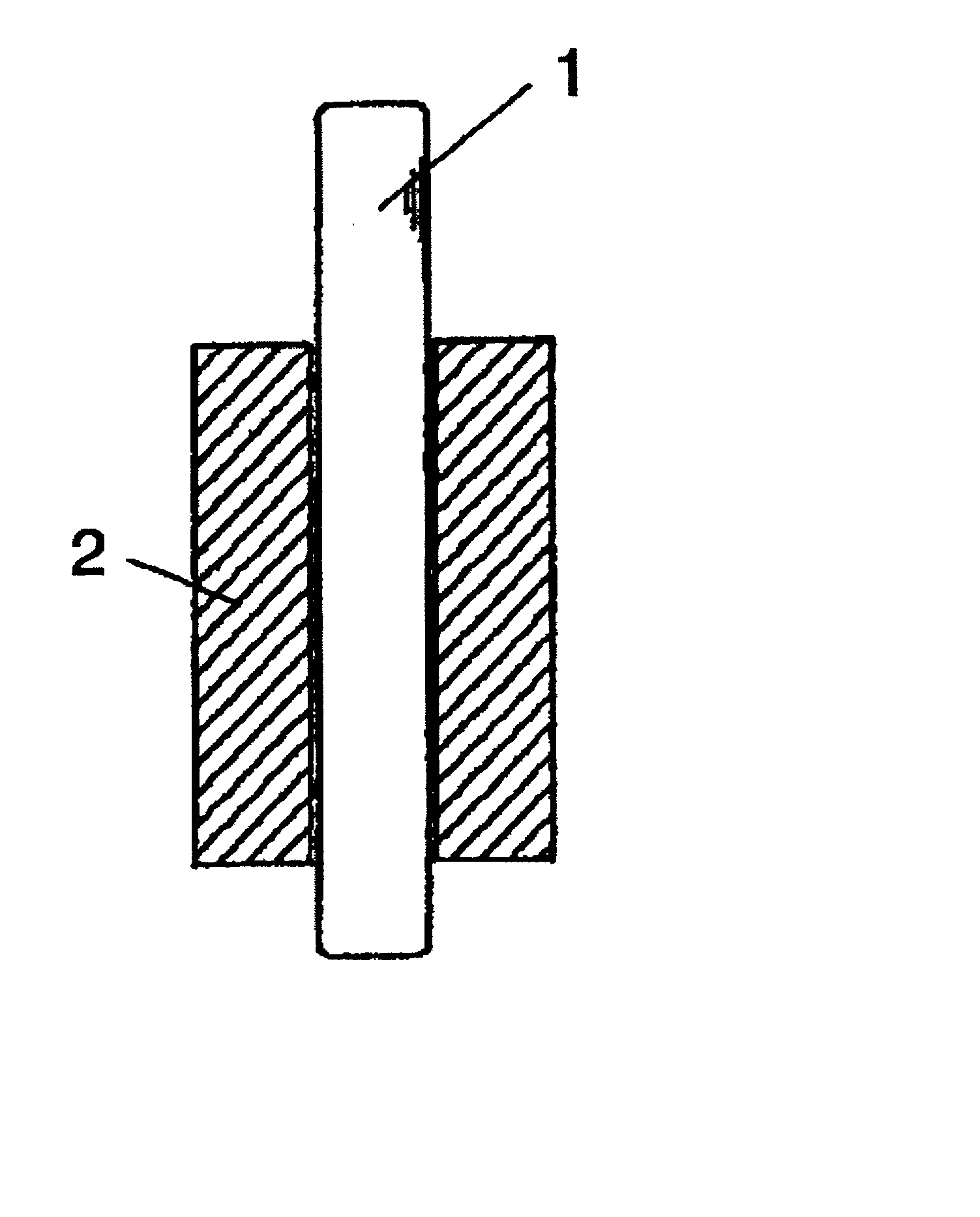
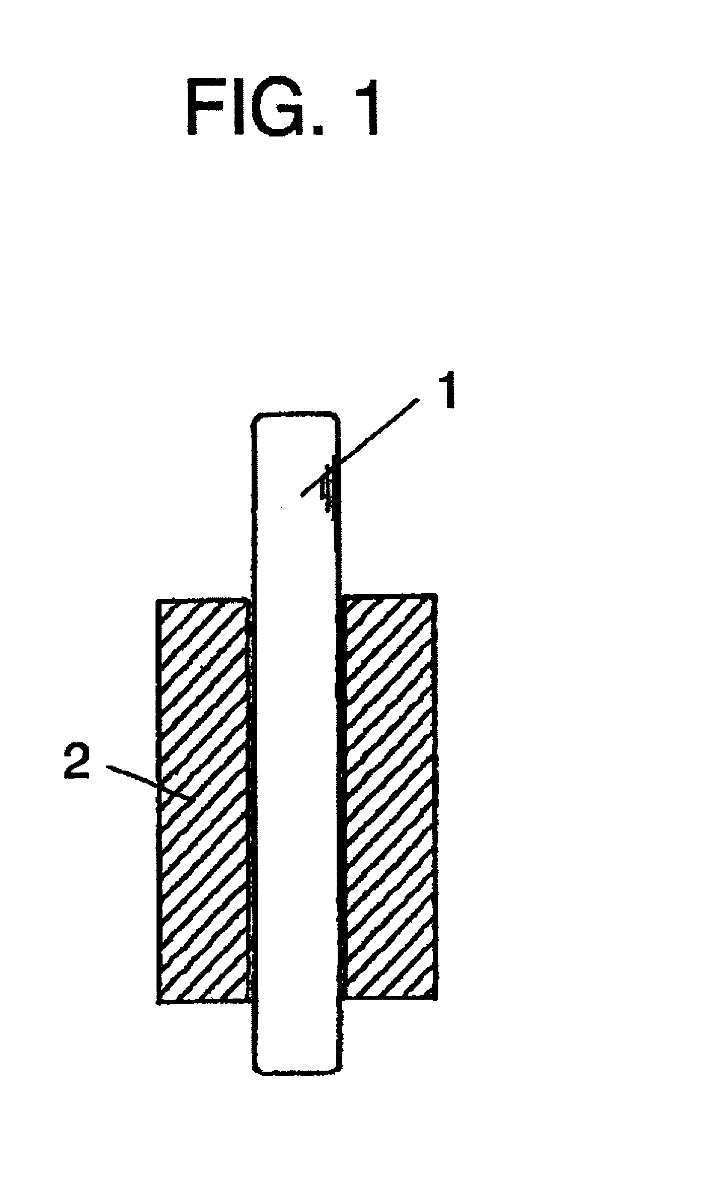
There is provided a maintenance-free sleeve bearing arrangement that is light in weight, has a long service life and does not require resupply of oil during operation. The sleeve bearing arrangement is comprised mainly of a shaft and a sleeve bearing, wherein the sleeve bearing formed of CRB ceramics, and / or the shaft formed of the CRB ceramics are used.
Description
[0001] 1. Field of the Invention[0002] The invention relates to a sleeve bearing arrangement using a new material, and more particularly, the invention provides a maintenance-free sleeve bearing that does not require resupply of oil during operation. At the same time, it is an object of the invention to provide a sleeve bearing using a high-tech eco-material (state-of-the-art material excellent in ecological adaptability) obtained from biomass type resources, different from conventional industrial material.[0003] 2. Description of the Related Art[0004] In the past, sleeve bearings made of resin such as polyacetal, polyamide, etc. have been in use for rotating parts which are light in weight and slow in rotation speed because such sleeve bearings are available at a low cost in comparison with sleeve bearings made of metal.[0005] However, as a lubricating oil is required between a shaft and a sleeve bearing, a method of lengthening a service life of the sleeve bearing has been under s...
Claims
Login to View More Application Information
Patent Timeline
 IPC IPC(8): F16C33/04F16C33/24F16C33/20
CPCF16C33/043
InventorHOKKIRIGAWA, KAZUOOBARA, RIKUROAKIYAMA, MOTOHARU
OwnerMINEBEAMITSUMI INC