Thermocompression bonding device and bonding head thereof

Inactive Publication Date: 2002-09-12
NAGAOKA TSUTOMU
View PDF0 Cites 2 Cited by
  • Summary
  • Abstract
  • Description
  • Claims
  • Application Information

AI Technical Summary

Benefits of technology

[0011] According to the present invention, the presence of the ceramic layer having a small thermal expansion coefficient on the contact part of the pressing member of the thermocompression-bonding head body can readily satisfy a required flatness tolerance without causing undulation on the head contact face of the ceramic layer even when it is heated at a temperature on the order of 300.degree. C. As a result, the present invention can greatly improve the yield of thermocompression bonded objects.
[0022] According to this aspect of the present invention, a thermocompression-bonding apparatus can be obtained which achieves a high yield of thermocompression bonded objects with simple maintenance without requiring any process for controlling contact of the thermocompression-bonding head or repolishing the head contact face or the like.

Problems solved by technology

However, these conventional thermocompression-bonding heads disadvantageously could not satisfy the required flatness tolerance resulting in low yields of thermocompression bonded objects because their thermal expansion properties caused undulation in the head contact faces of their pressing members at thermocompression-bonding temperatures on the order of 300.degree. C.
Conventional thermocompression-bonding heads made of Ni--Co alloys were insufficient in the wear resistance of the head contact faces of their pressing members, and as a result, they were difficult to maintain a required flatness during a long-period of use so that the thermocompression-bonding heads had to be repolished every a few months.
Moreover, the above Ni--Co alloys were poor in cutting processability to increase the processing cost.

Method used


Image

  • Thermocompression bonding device and bonding head thereof
  • Thermocompression bonding device and bonding head thereof
  • Thermocompression bonding device and bonding head thereof

Examples


Embodiment Construction

[0028] An embodiment of a thermocompression-bonding head according to the present invention and a thermocompression-bonding apparatus using it will now be described in detail with reference to the accompanying drawings.

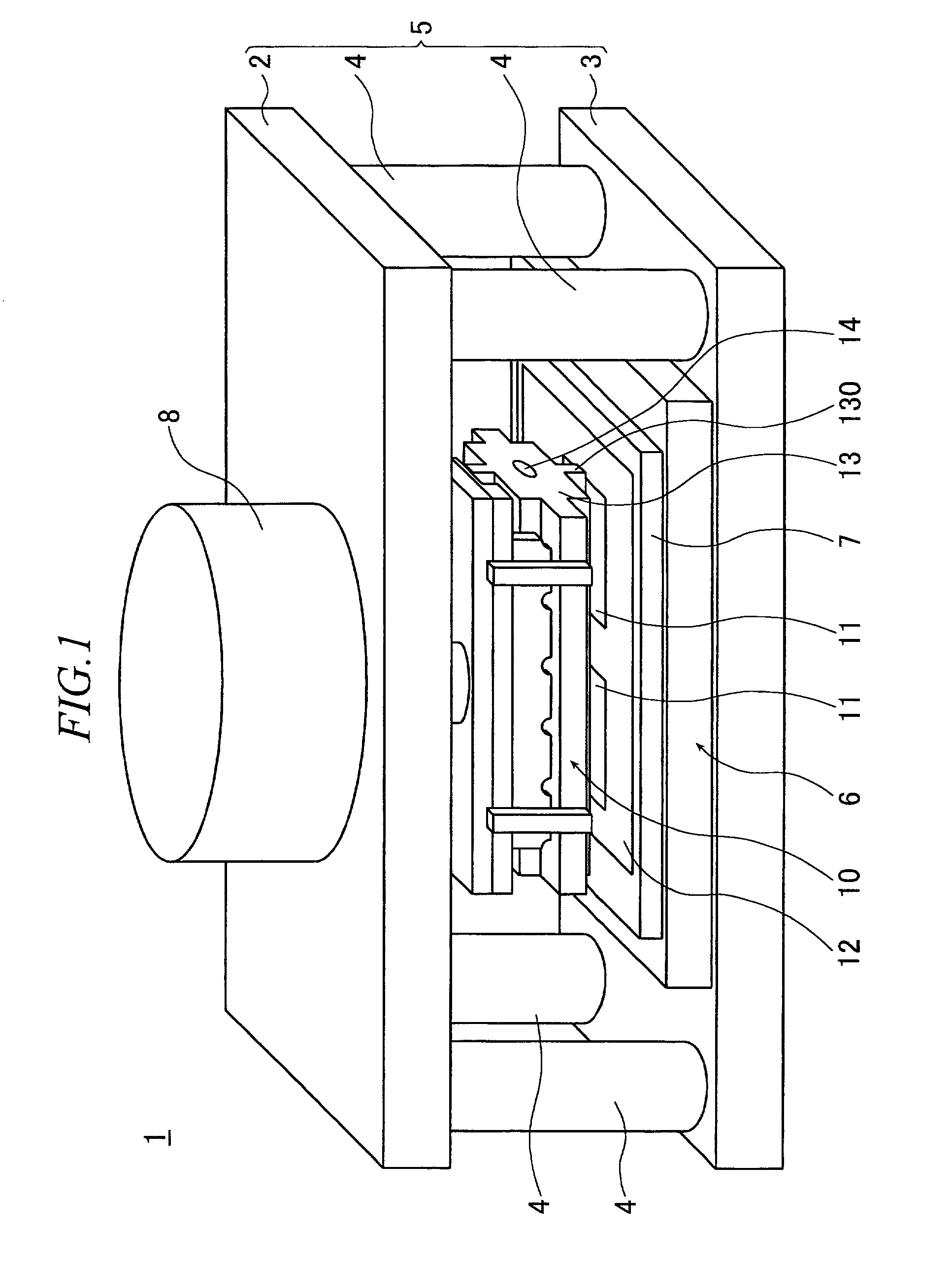
[0029] As shown in FIG. 1, a thermocompression-bonding apparatus 1 of the present invention has a body frame 5 comprising a pair of upper and lower frames in parallel 2, 3 and connecting shafts 4 for connecting said upper and lower frames 2, 3.

[0030] A single axis robotic table 6 is provided on the lower frame 3. The single axis robotic table 6 can position a table 7 made of a heat-resistant material at a predetermined position.

[0031] On the upper frame 2 is provided an air cylinder 8, which can press a thermocompression-bonding head 10 of the present invention into a vertically downward direction.

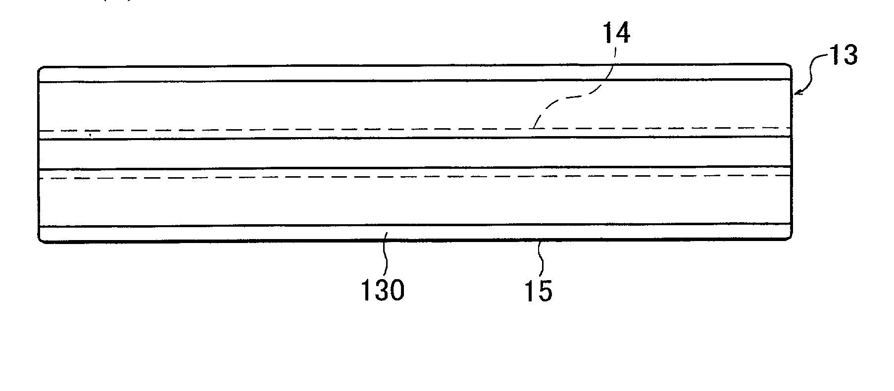
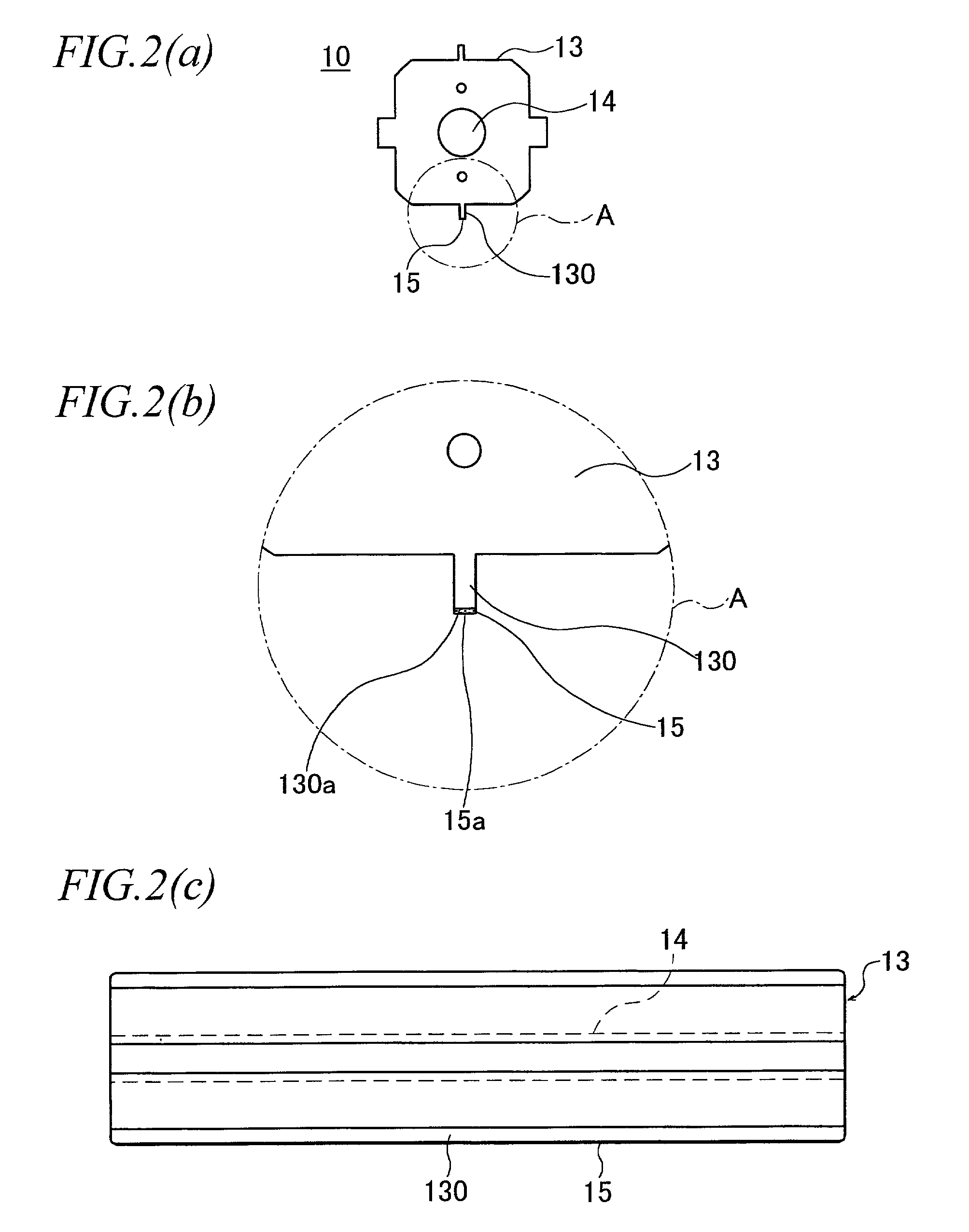
[0032] As shown in FIG. 1, a glass substrate 12 having a plurality of flexible substrates 11 provisionally compression-bonded thereto with an anisotropic conductive adhesive...


PUM

PropertyMeasurementUnit
Temperatureaaaaaaaaaa
Fractionaaaaaaaaaa
Thicknessaaaaaaaaaa

Abstract

The thermocompression-bonding head (10) of the thermocompression-bonding apparatus (1) according to the present invention has a ceramic layer (15) having a predetermined thickness on the contact part (130a) of the pressing member (130) of the head body (13). The difference between the thermal expansion coefficient of the head body (13) and the thermal expansion coefficient of the ceramic layer (15) is within the range of ±30% at a temperature of 400° C. or less.

Description

[0001] The present invention relates to a thermocompression-bonding head used for establishing interconnections between connecting terminals using, for example, an anisotropic conductive adhesive film or an insulating adhesive film.PRIOR ART[0002] Interconnections between connecting terminals using an anisotropic conductive film (ACF) or the like have conventionally been established by inserting said anisotropic conductive film or the like between said connecting terminals to join them under heating and pressure by a pressing head heated at a predetermined temperature.[0003] Such a thermocompression-bonding head is required to have a head contact face maintained within a flatness tolerance of 0.005 mm at a temperature on the order of 300.degree. C. for a long period.[0004] Fe--Ni--Co or the like alloys have conventionally been used as materials for thermocompression-bonding heads satisfying the above condition.[0005] However, these conventional thermocompression-bonding heads disadv...

Claims


Application Information

Patent Timeline
IPC IPC(8): G02F1/1345H01L21/00H01L21/60H01L21/603H05K3/32
CPCH01L21/67144H01L21/60
Inventor NAGAOKA, TSUTOMU
Owner NAGAOKA TSUTOMU
Why Eureka
Try Eureka