Conveyor belt cleaning system

a conveyor belt and cleaning technology, applied in the direction of cleaning, conveyor parts, transportation and packaging, etc., can solve the problems of reducing the contacting force of the belt, and reducing the cleaning efficiency of the scraper blade assembly,

Inactive Publication Date: 2002-09-12
MARTIN ENG
View PDF0 Cites 9 Cited by
  • Summary
  • Abstract
  • Description
  • Claims
  • Application Information

AI Technical Summary

Benefits of technology

[0019] Another feature of the invention is that the scraper blade is positioned directly above the center of the carrier shaft thereby creating a more positive cleaning pressure and improving the cleaning capabilities of the torsion blade holder assembly.
[0020] Another feature of the invention is that the torsion blade holder assembly can be adapted to accept a means for spraying a liquid, e.g., water, anti-freeze, or dust prohibitor, onto the belt, thereby diluting the material and debris on the belt before the blade comes into contact with the surface of the belt or treating the surface of the conveyor belt after it has been cleaned.
[0021] An advantage of the invention is that the vertical blade stabilizers provide an added measure of support for the scraper blade in addition to traditional mounting bolts that secure the scraper blade to the face plate.
[0022] Another advantage of the invention is that decrease in the vibration of the scraper blade increases the useful life of the scraper blade and torsion blade holder assembly, and also improves their cleaning abilities.
[0023] Another advantage of the invention is that, due to the increased range of rotation of the scraper blade, larger obstructions adhered to the conveyor belt are able to pass the torsion blade holder assembly thereby increasing the useful life of the scraper blade as well as the and torsion blade holder assembly.

Problems solved by technology

As the scraper blades wear down, the contacting force on the belt steadily decreases, thereby reducing the cleaning efficiency of the scraper blade assembly.
After prolonged use, standard clamps and set screws become ineffective to maintain and adjust the contacting force.
A further problem with this method is that it is not possible to adjust a single scraper blade, i.e., an adjustment to one is an adjustment to all because it is the shaft on which the scraper blades are mounted that is adjusted.
A still further problem is that the scraper blades undergo significant stress from vibrations resulting from the fact that the blades are only bolted or screwed directly on to the face of the assembly.
In addition to the above, conventional blade assemblies do not provide any means for loosening or diluting debris on a conveyor belt prior to scraping the conveyor belt with a blade assembly.

Method used


Image

  • Conveyor belt cleaning system
  • Conveyor belt cleaning system
  • Conveyor belt cleaning system

Examples


Embodiment Construction

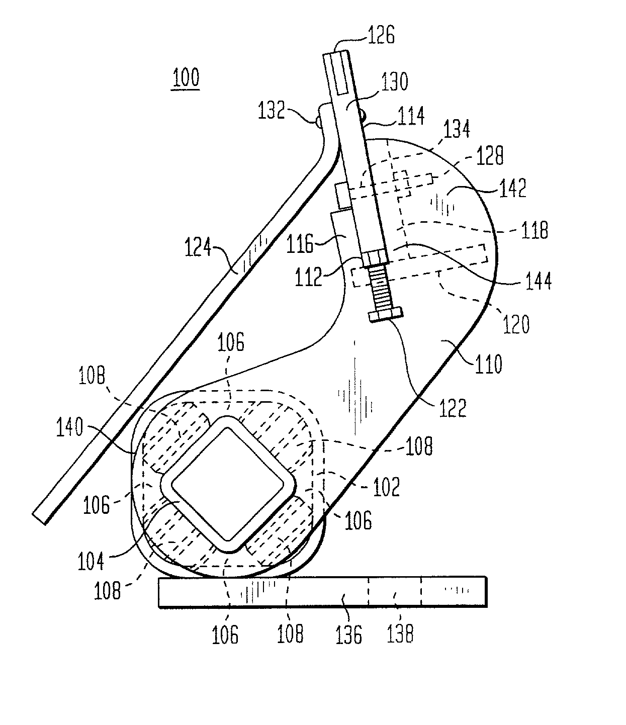
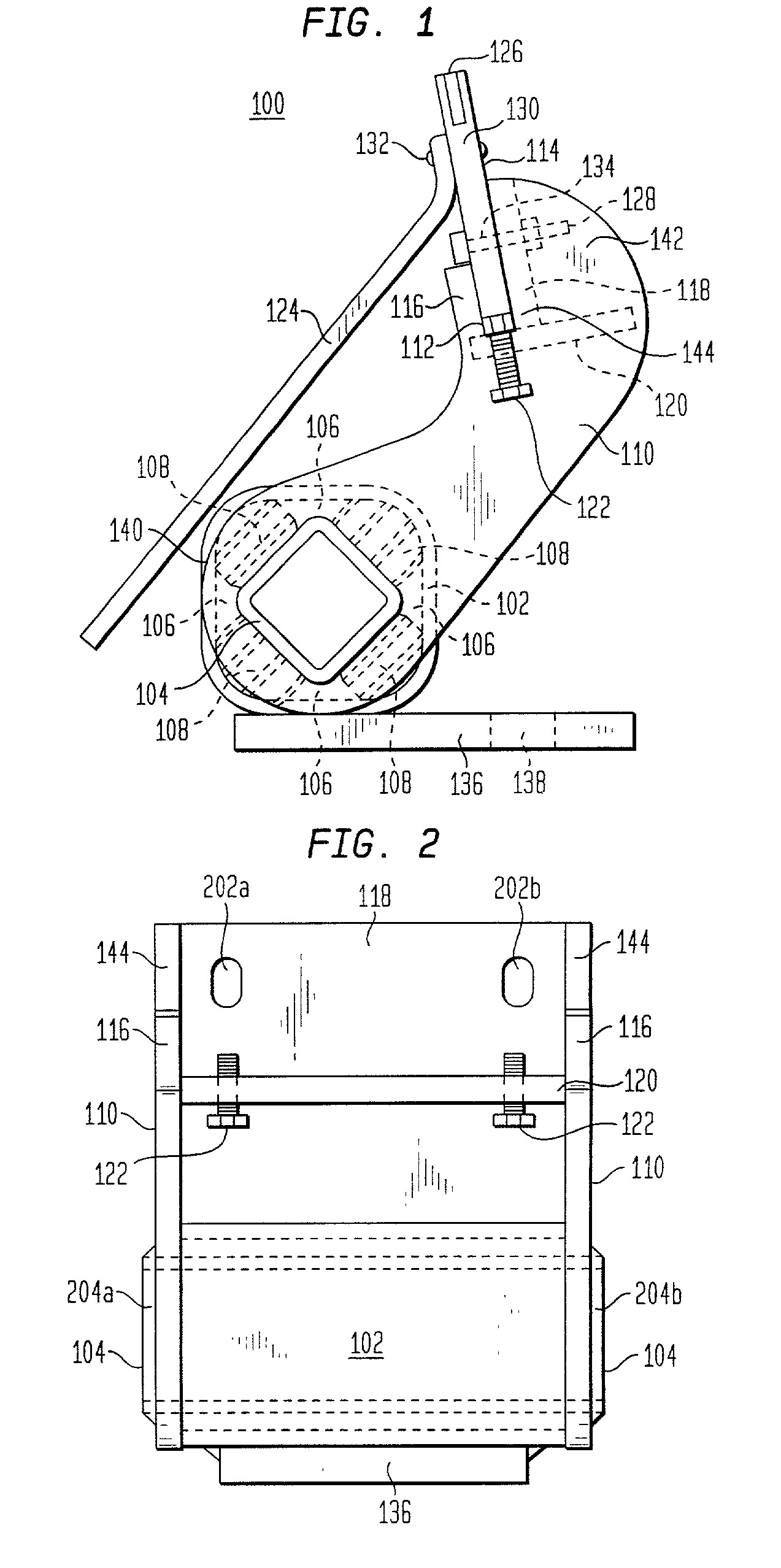
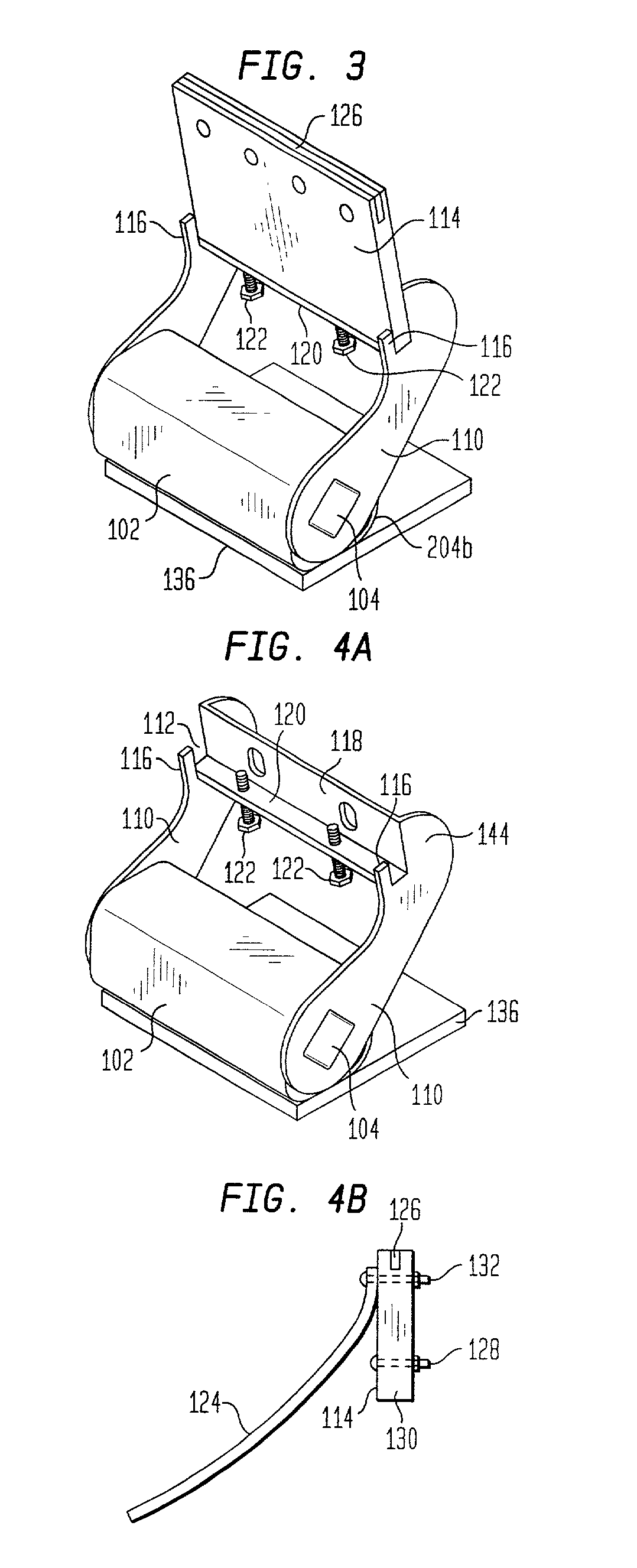
[0036] FIGS. 1-4B show an exemplary embodiment of the torsion blade holder assembly 100 of the present invention, FIGS. 5A-D show an alternative embodiment adapted for use with a means for spraying a liquid on a conveyor belt either prior to or after scraping, and FIGS. 6-8 illustrate various alternative embodiments of the present invention. The torsion blade holder assembly 100 of the present invention comprises two sub-assemblies: a mounting sub-assembly and a blade support sub-assembly, wherein the blade support sub-assembly is connected to the mounting sub-assembly and the mounting sub-assembly secures the blade support assembly (and thereby secures the torsion blade holder assembly 100) to a shaft such that a surface of a conveyor belt travels over and in contact with a scraper blade 114 within the blade support sub-assembly as a means for cleaning the surface of the conveyor belt.

[0037] In the preferred embodiment, the mounting sub-assembly employs torsion means for allowing t...


PUM


Abstract

A conveyor belt cleaning system being a torsion blade holder assembly having a mounting sub-assembly and a blade support sub-assembly. The mounting sub-assembly has a first hollow member and a second member situated at least partially therein with torsion elements in the plurality of spaces or cavities between the first hollow member and the second member. The blade support sub-assembly, in which a scraper blade is secured, is attached to the second member such that when the scraper blade meets resistance while scraping the surface of a conveyor belt, the torsion elements are compressed and the blade support sub-assembly with the scraper blade rotates away from the conveyor belt. The blade support sub-assembly includes notched receiving members for receiving the scraper blade, a face plate extending between the notched receiving members approximately parallel to the scraper blade such that at least a portion of the scraper blade rests flush against the face plate when the scraper blade is situated in the notched receiving members, a horizontal blade stabilizer approximately perpendicular to and extending beneath the face plate, and a means for vertically adjusting the scraper blade within the notched receiving members. The means for vertically adjusting is one or more adjustable lock bolts extending upward through the horizontal blade stabilizer for adjusting the scraper blade up and down within the notched receiving members. The torsion blade holder assembly optionally includes a shield and a means for spraying a liquid on the conveyor belt.

Description

[0001] This application claims the benefit of U.S. application Ser. No. 60 / 270,825, filed Feb. 22, 2001.[0002] 1. Field of the Invention[0003] This invention relates to conveyor belts, and, more particularly, to scraper blades for cleaning conveyor belts.[0004] 2. Related Art[0005] Conveyor belts are often used to convey materials that adhere to the surface of the belt. In order to maintain efficient operation of the conveyor belt system, the excess debris must be removed from the surface of the belt. Accordingly, there are various types of scraper blade assemblies that are used to scrap the debris from a surface of a conveyor belt.[0006] A common type of scraper blade assembly comprises a plurality of mounted scraper blades extending across the transverse axis of the conveyor belt. The blade assemblies are mounted on support arms which are fixed to and extend from a transverse rotatable support shaft. Rotation of the transverse support shaft moves the scraper blades into and out of...

Claims


Application Information

Patent Timeline
Patent Type & Authority Applications(United States)
IPC IPC(8): B65G45/16
CPCB65G45/16
Inventor HALL, JOHN
Owner MARTIN ENG
Why Eureka
Try Eureka