
Diversity antenna on a dielectric surface in a motor vehicle body

a technology of diversity antenna and dielectric surface, which is applied in diversity/multi-antenna systems, independent non-interfering antenna combinations, transportation and packaging, etc., can solve the problems of insufficient installation space of this system, high installation cost, and high wiring cost, and achieve the effect of good reception quality

Inactive Publication Date: 2002-09-12
DELPHI DELCO ELECTRONICS EUROPE GMBH
View PDF0 Cites 72 Cited by
  • Summary
  • Abstract
  • Description
  • Claims
  • Application Information

AI Technical Summary

Benefits of technology

[0011] Therefore, the present invention provides an installation space-saving diversity antenna for a diversity antenna system in a motor vehicle, with received signals that can be selected in different ways. With this design, the average quality of the reception is as good as possible. In addition, the reception disturbances occur simultaneously in the different antenna signals while driving are kept as small as possible.

Problems solved by technology

Their connection to the body of the vehicle in the site of installation, and their wiring, would be connected with considerable expenditure, and would also be very complicated.
The installation space of this system is consequently not available because of the relatively large wavelengths of the useful frequency ranges.

Method used


Image

  • Diversity antenna on a dielectric surface in a motor vehicle body
  • Diversity antenna on a dielectric surface in a motor vehicle body
  • Diversity antenna on a dielectric surface in a motor vehicle body

Examples


Embodiment Construction

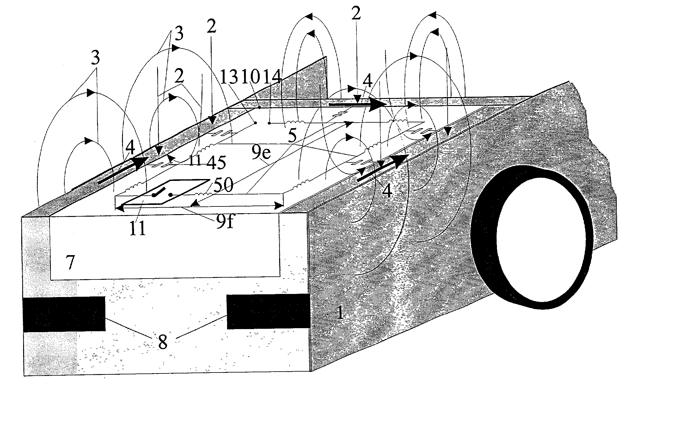
[0040] In the present invention, a multitude of antenna signals that are different in terms of diversity can be generated with only one conductor structure, which is installed in the marginal zone of the dielectric surface in a space-saving manner, and with only one connection network. Electronically controllable impedance networks requiring no ground connection to the vehicle can be provided in a simple and space-saving manner. Furthermore, it is also advantageous that the mobility of the trunk lid is not restricted since the electronically controllable impedance networks do not have to be grounded to the car.

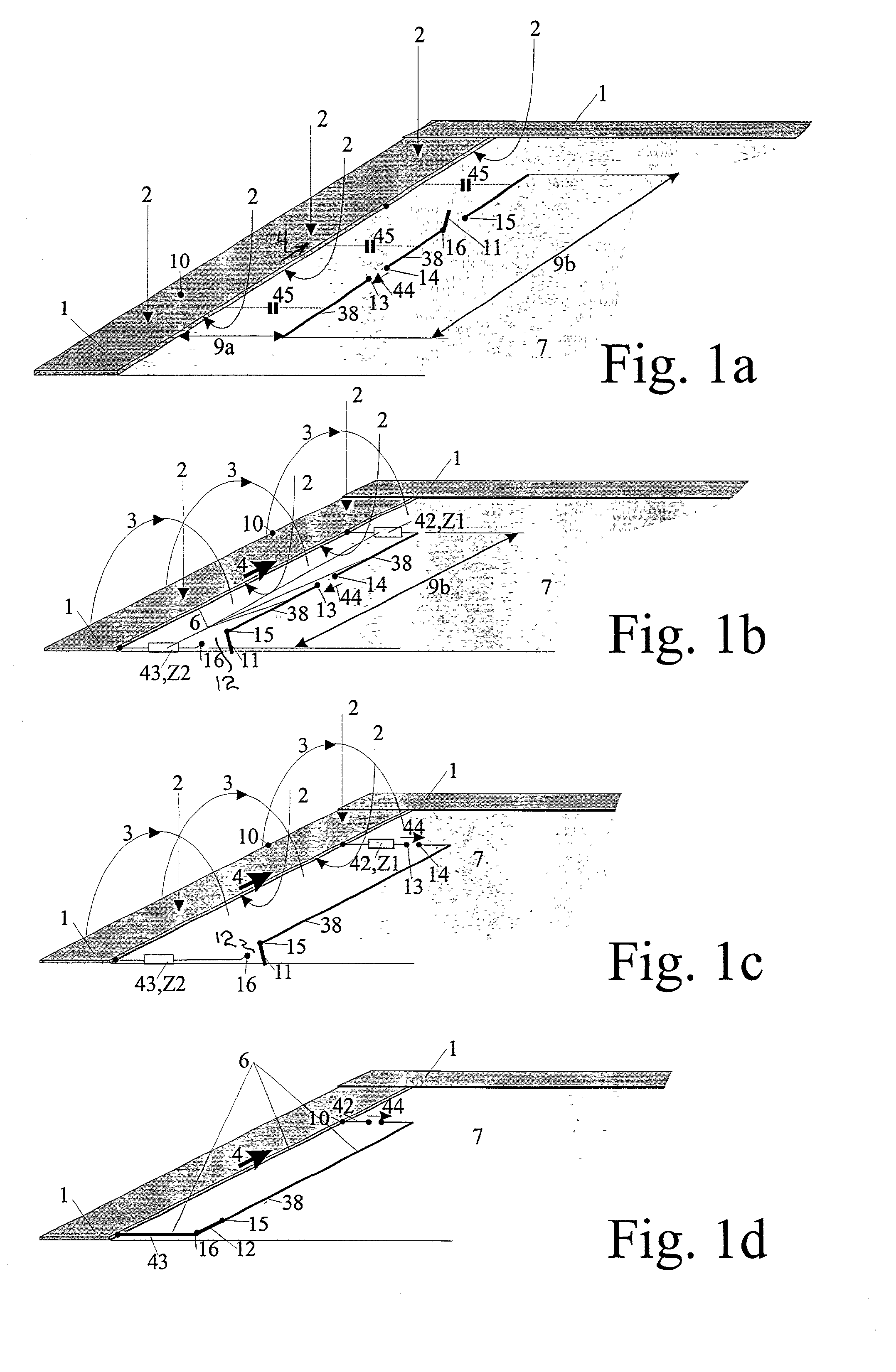
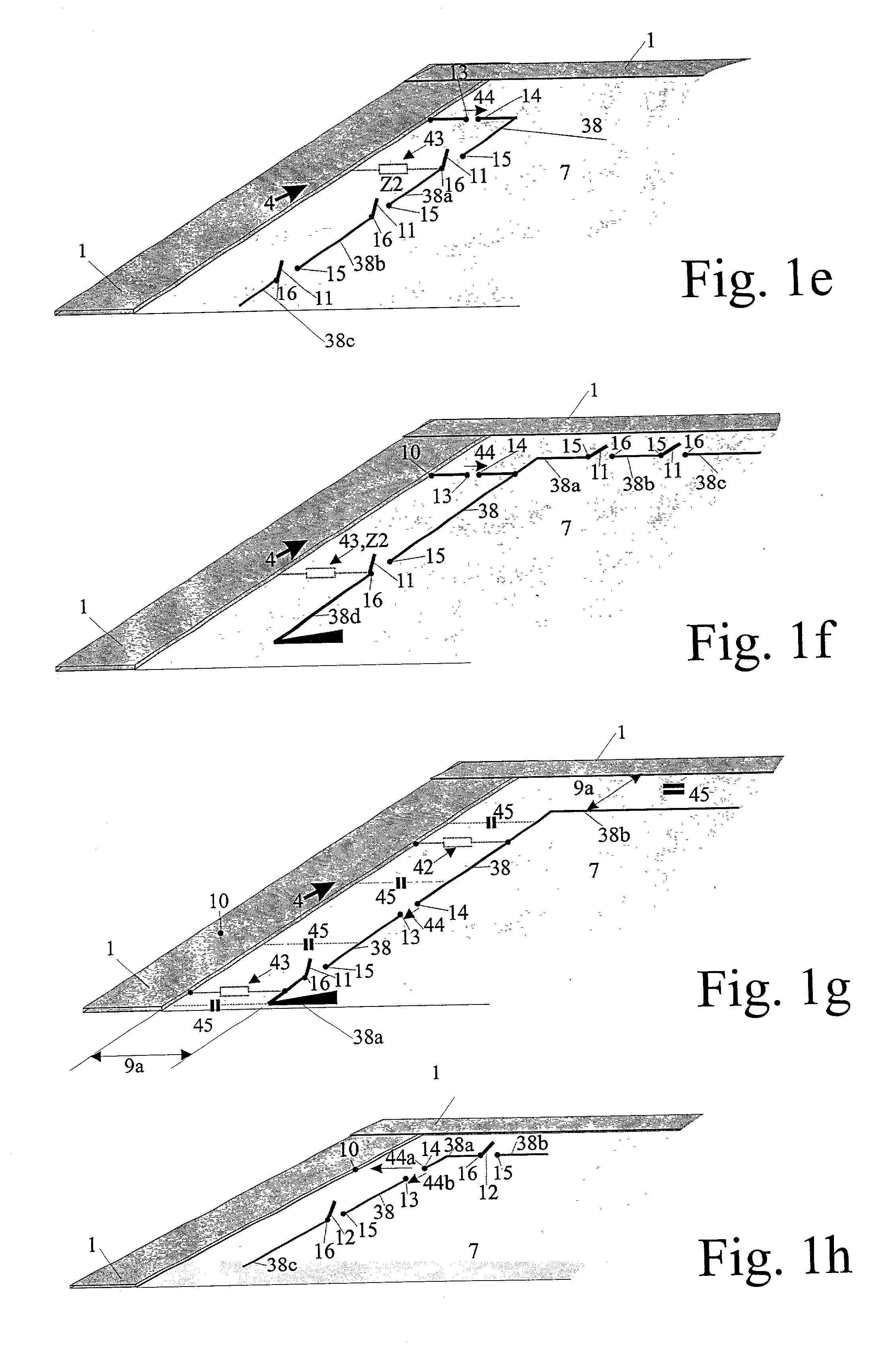
[0041] The mode of operation of the invention is described in the basic configurations of antennas shown in FIGS. 1a 1h. In FIG. 1a, a wire-shaped antenna conductor 38, having a length 9b is installed on a dielectric surface 7, and extends with a spacing 9a parallel with a conductive frame 1. Because of the concentration of electrical field lines 2 and magnetic field lines 3 (...


PUM


Abstract

A diversity antenna for the meter and decimeter wave ranges installed on a conductively framed dielectric surface in the body of a motor vehicle and substantially assembled from rectangular part surfaces, for example in a roof cutout or trunk with a dielectric trunk lid. A substantially wire-shaped antenna conductor is installed parallel with the conductive frame and spaced from a part thereof of the dielectric surface less than one fourth of the width of the dielectric surface. The wire-shaped antenna conductor has an interruption site which define a pair of antenna connection terminals. A two-pole, electronically controllable impedance network is incorporated in series in at least one additional interruption site. The position of the interruption site with the pair of antenna connection terminals, and the position of the additional interruption site are selected so that the antenna signals available at the different settings of the controllable impedance network are adequately decoupled in terms of diversity.

Description

BACKGROUND[0001] 1. Field of the Invention[0002] The invention relates to a multi-antenna diversity antenna system installed on a conductively framed, dielectric surface in the body of a motor vehicle. This antenna system is for receiving signals in the meter and decimeter wave ranges, for example for radio or television broadcast reception.[0003] 2. The Prior Art[0004] Conventional multi-antenna systems are described, for example in European patent EP 0 269 723, and German patents DE 36 18 452; DE 39 14 424, FIG. 14; DE 37 19 692; and P 36 19 704, for windshield and rear window glass panes.[0005] With an adequate high-frequency decoupling of the antennas, reception disturbances occur when the motor vehicle is positioned in different locations in the field of reception. These receiver disturbances occur with temporary level fading events due to the multi-directional propagation of the electromagnetic waves. This effect is explained by way of example in FIGS. 3 and 4 in EP 0 269 723....

Claims


Application Information

Patent Timeline
Patent Type & Authority Applications(United States)
IPC IPC(8): B60R11/02B60J1/00H01Q1/22H01Q1/32H01Q1/52H01Q21/28H04B7/08
CPCH01Q1/32H01Q1/3275H01Q21/28
Inventor LINDENMEIER, HEINZHOPF, JOCHENREITER, LEOPOLD
Owner DELPHI DELCO ELECTRONICS EUROPE GMBH
Learn More