Ultrasonic liquid-crystal display

Inactive Publication Date: 2002-09-12
TODA KOHJI
View PDF0 Cites 1 Cited by
  • Summary
  • Abstract
  • Description
  • Claims
  • Application Information

AI Technical Summary

Benefits of technology

[0006] Another object of the present invention is to provide an ultrasonic liquid-crystal display excellent in durability and manufacturing.
[0007] Another object of the present invention is to provide an ultrasonic liquid-crystal display operating with a quick response time.
[0008] Another object of the present invention is to provide an ultrasonic liquid-crystal display operating under low electric power consumption with low voltage.
[0009] Another object of the present invention is to provide an ultrasonic liquid-crystal display excellent in the range of vision.
[0010] Another object of the present invention is to provide an ultrasonic liquid-crystal display without the inferiority in liquid crystal.
[0013] A still other object of the present invention is to provide an ultrasonic liquid-crystal display having a small size and a simple structure which is very light in weight.

Problems solved by technology

However, it is unavoidable that an electric power consumption to the backlight is 70.about.80% of all the electric power consumption to the display.
Using reflective-type displays in place of nonreflective-type displays such as the TFT-type display cause a decrease in electric power.
The reflective-type displays, for example, polymer dispersed display and guest-host mode display have problems on response time, accuracy and clearness, durability and manufacturing, electric power consumption, range of vision, inferiority in liquid crystal, and device size.
On the other side, dynamic scattering mode display, which is the initial type, is not adequate for practical use at present.

Method used


Image

  • Ultrasonic liquid-crystal display
  • Ultrasonic liquid-crystal display
  • Ultrasonic liquid-crystal display

Examples


first embodiment

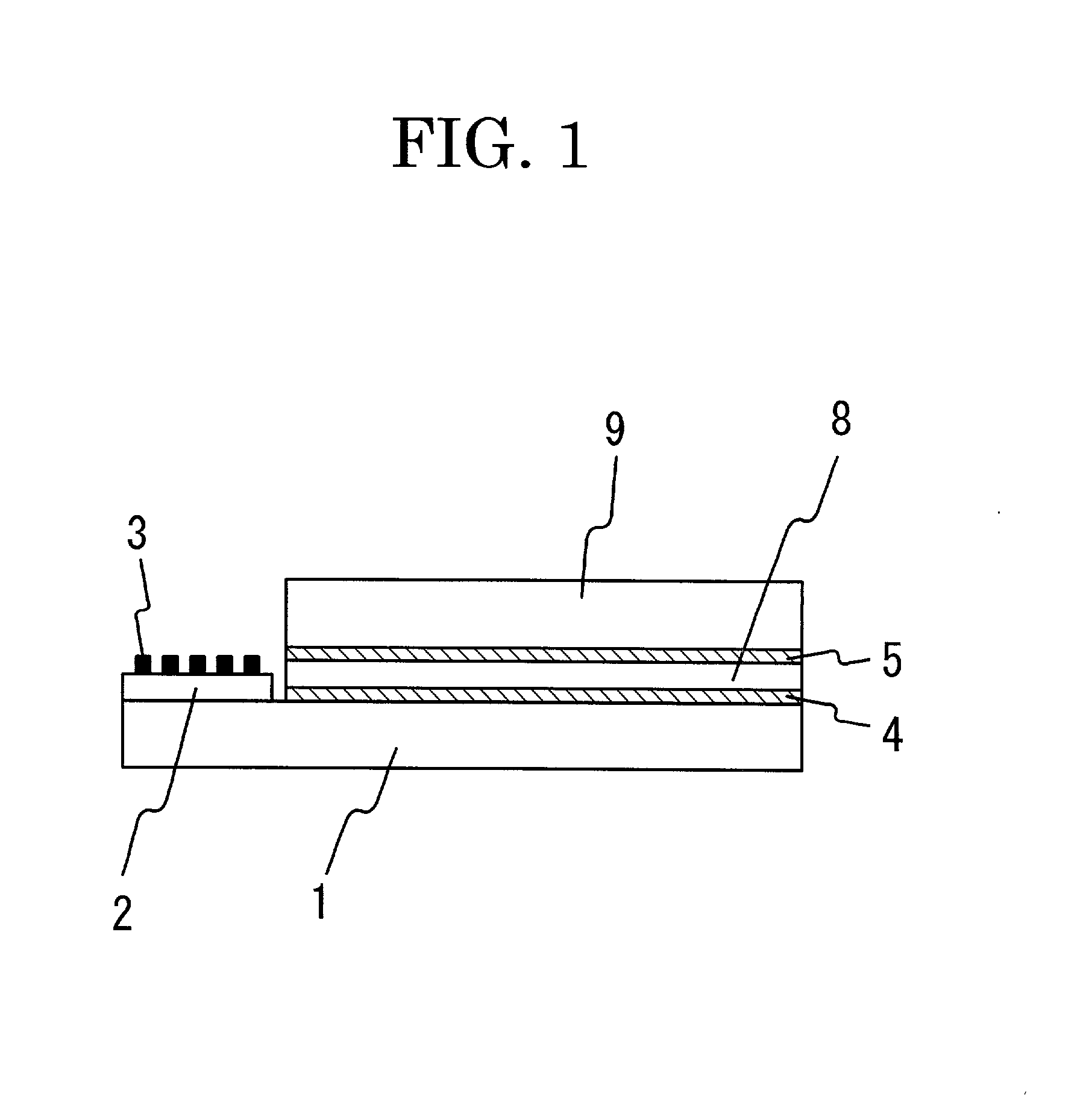
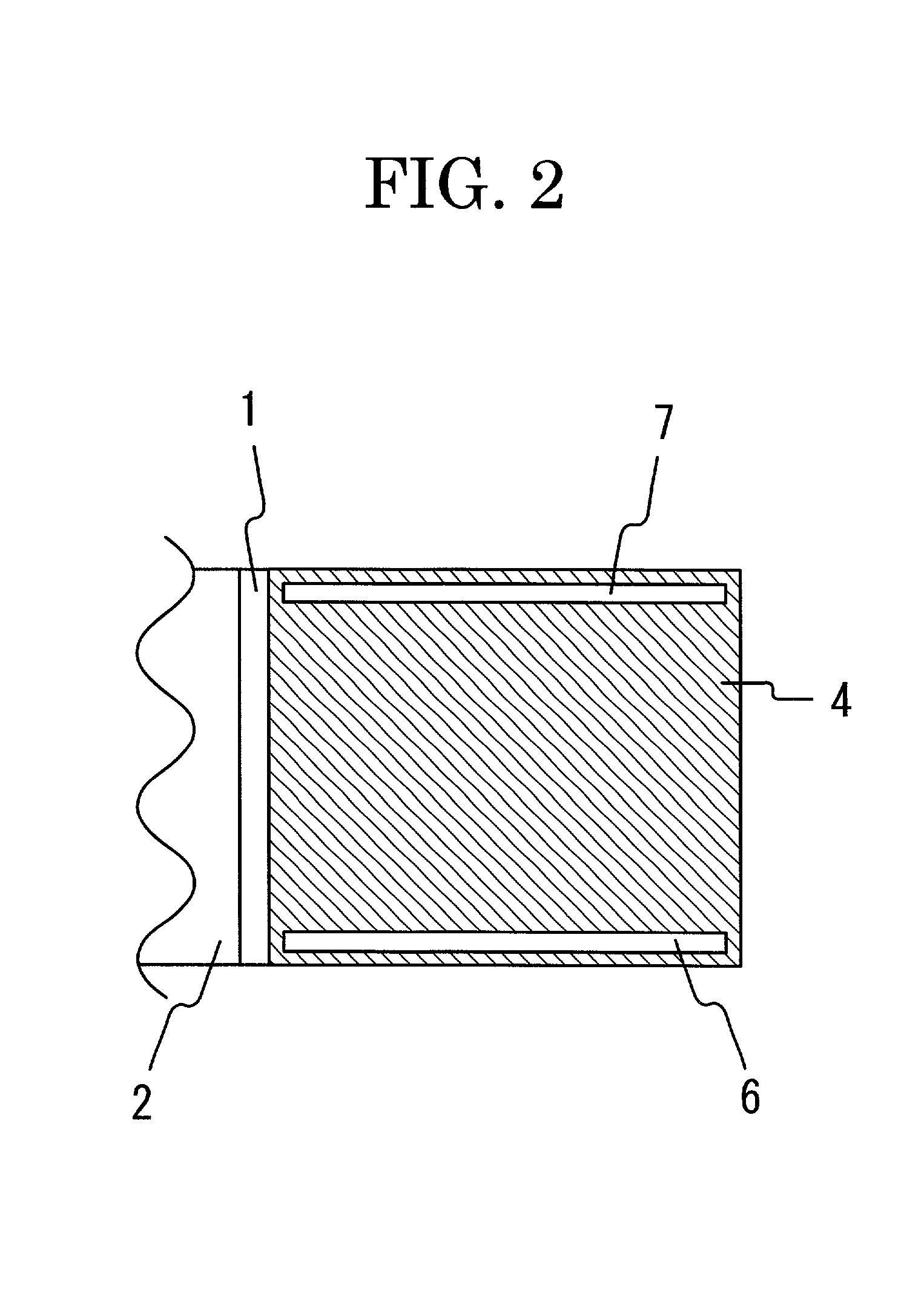
[0047] FIG. 1 shows a sectional view of an ultrasonic liquid-crystal display according to the present invention. The ultrasonic liquid-crystal display comprises nonpiezoelectric bottom-plate 1, piezoelectric substrate 2, dispersive interdigital transducer 3, first conducting electrode 4, second conducting electrode 5, first spacer 6, second spacer 7, liquid crystal 8, and nonpiezoelectric upper-plate 9. First spacer 6 and second spacer 7 are not drawn in FIG. 1. Nonpiezoelectric bottom-plate 1 and nonpiezoelectric upper-plate 9, made of transparent glass plates, have a dimension of 1.1 mm in thickness, respectively. The phase velocity of the SAW traveling on nonpiezoelectric bottom-plate 1 alone is higher than that traveling on piezoelectric substrate 2 alone. Piezoelectric substrate 2 is made of a piezoelectric ceramic thin plate with a dimension of 230 .mu.m in thickness, and the polarization axis thereof is parallel to the thickness direction thereof. Dispersive interdigital tran...

second embodiment

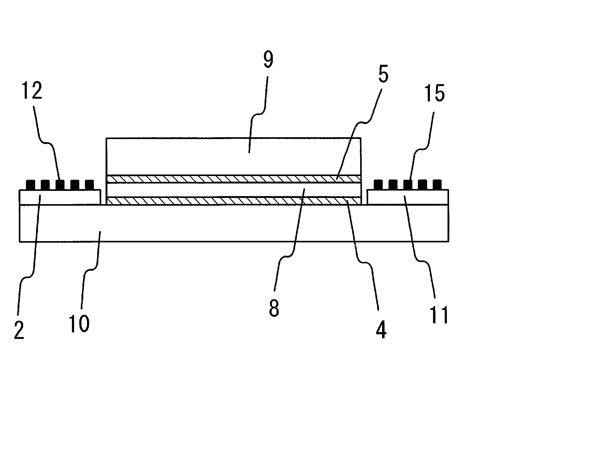
[0057] FIG. 8 shows a sectional view of an ultrasonic liquid-crystal display according to the present invention. The ultrasonic liquid-crystal display comprises nonpiezoelectric bottom-plate 10, piezoelectric substrate 2, another piezoelectric substrate 11, dispersive interdigital transducers 12, 13 and 14, input interdigital transducers 15, 16 and 17, first conducting electrode 4, second conducting electrode 5, first spacer 6, second spacer 7, liquid crystal 8, and nonpiezoelectric upper-plate 9. First spacer 6, second spacer 7, dispersive interdigital transducers 13 and 14, and input interdigital transducers 16 and 17 are not drawn in FIG. 8. Nonpiezoelectric bottom-plate 10 is made of the same material and has the same thickness as nonpiezoelectric bottom-plate 1. Piezoelectric substrate 11 is made of the same material and has the same size as piezoelectric substrate 2. Dispersive interdigital transducers 12, 13 and 14 are formed on piezoelectric substrate 2, which is formed on a...

third embodiment

[0060] FIG. 10 shows a sectional view of an ultrasonic liquid-crystal display according to the present invention. The ultrasonic liquid-crystal display comprises nonpiezoelectric bottom-plate 10, piezoelectric substrate 2, piezoelectric substrate 11, dispersive interdigital transducers 12, 13 and 14, output interdigital transducers 18, 19 and 20, amplifier 21, switch 22, mirror 23, first conducting electrode 4, second conducting electrode 5, first spacer 6, second spacer 7, liquid crystal 8, and nonpiezoelectric upper-plate 9. First spacer 6, second spacer 7, dispersive interdigital transducers 13 and 14, output interdigital transducers 19 and 20, amplifier 21, and switch 22 are not drawn in FIG. 10. Piezoelectric substrate 2, first conducting electrode 4, and piezoelectric substrate 11 are formed on first-, second-, and third surface parts, respectively, of an upper end-surface of nonpiezoelectric bottom-plate 10. Dispersive interdigital transducers 12, 13 and 14 are formed on piez...


PUM


Abstract

An ultrasonic liquid-crystal display comprises a nonpiezoelectric bottom-plate, a piezoelectric substrate on a first surface-part of an upper end-surface of the nonpiezoelectric bottom-plate, at least one dispersive interdigital transducer on the piezoelectric substrate, a nonpiezoelectric upper-plate, a first conducting electrode, with which a second surface-part of the upper end-surface of the nonpiezoelectric bottom-plate is covered, a second conducting electrode, with which a lower end-surface of the nonpiezoelectric upper-plate is covered, and a liquid crystal between the first- and second conducting electrodes. The nonpiezoelectric bottom-plate and the nonpiezoelectric upper-plate have a transparency, respectively. When a first electric signal is applied to the dispersive interdigital transducer, an FM chirp-SAW is excited in the piezoelectric substrate. The FM chirp-SAW transmitted to the liquid crystal causes it cloudy. Supplying the first- and second conducting electrodes with a second electric signal, that is, applying electric field to the liquid crystal, makes the liquid crystal cloudless.

Description

[0001] 1. Field of the Invention[0002] The present invention relates to an ultrasonic liquid-crystal display by means of using a dispersive interdigital transducer on a piezoelectric substrate formed on a first surface-part of a nonpiezoelectric bottom-plate, a sandwich formed on a second surface-part of the nonpiezoelectric bottom-plate and composed of a liquid crystal between first- and second conducting electrodes, and a nonpiezoelectric upper-plate on the sandwich.[0003] 2. Description of the Prior Art[0004] In recent years, liquid-crystal displays act important parts on computers, portable communication devices, and so on. The thin-film transistor (TFT)-type liquid-crystal display, which is a popular one of conventional liquid-crystal displays, is good in quality. However, it is unavoidable that an electric power consumption to the backlight is 70.about.80% of all the electric power consumption to the display. Using reflective-type displays in place of nonreflective-type displa...

Claims


Application Information

Patent Timeline
IPC IPC(8): G02F1/133
CPCG02F1/13306
Inventor TODA, KOHJI
Owner TODA KOHJI
Why Eureka
Try Eureka