Device for measuring sound velocity in material
a technology of sound velocity and material, applied in the direction of heat measurement, specific gravity measurement, instruments, etc., can solve the problems of difficult use and measurement accuracy, complicated circuit construction, and difficulty in conventional transducer quick response measuremen
- Summary
- Abstract
- Description
- Claims
- Application Information
AI Technical Summary
Benefits of technology
Problems solved by technology
Method used
Image
Examples
first embodiment
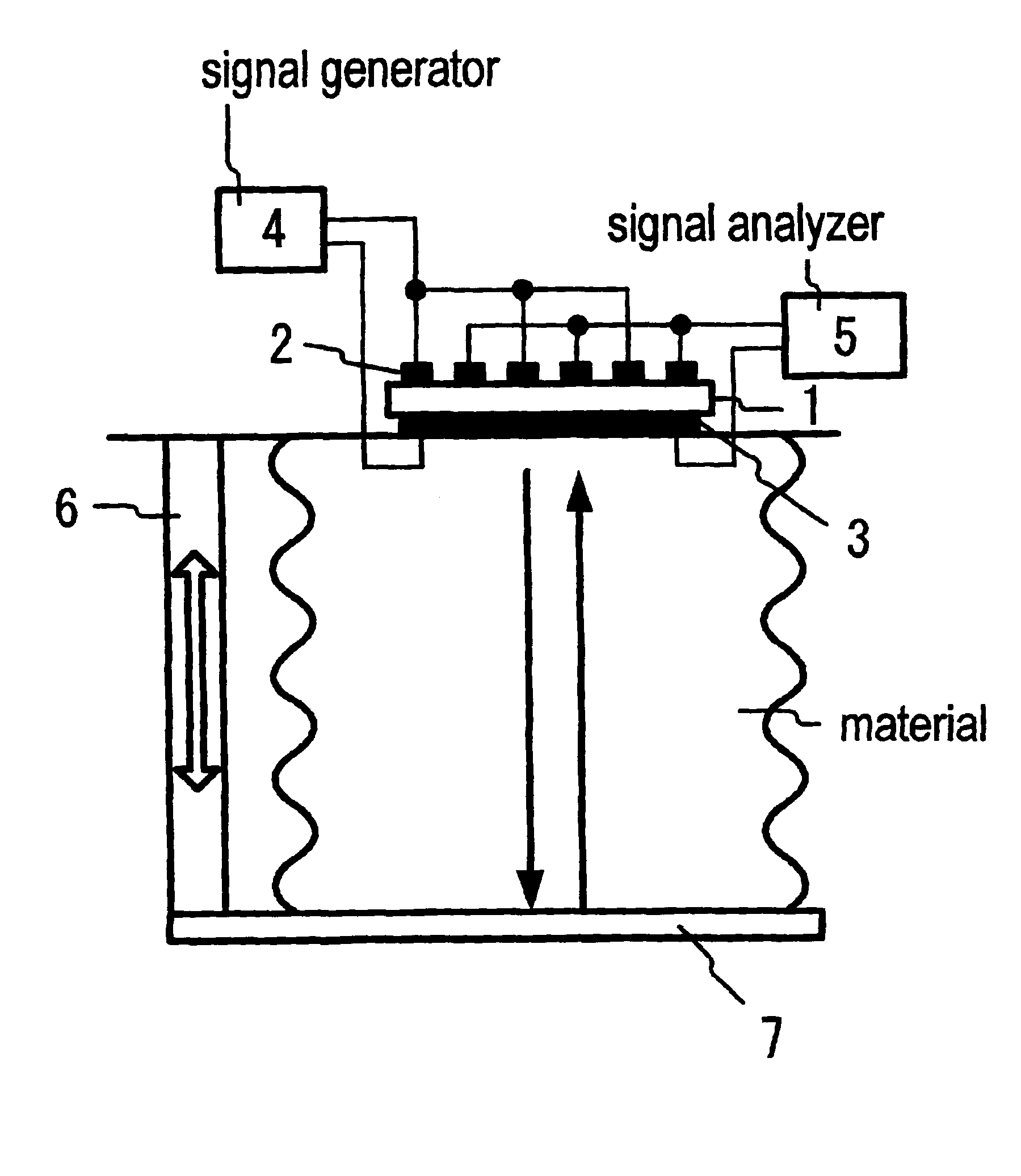
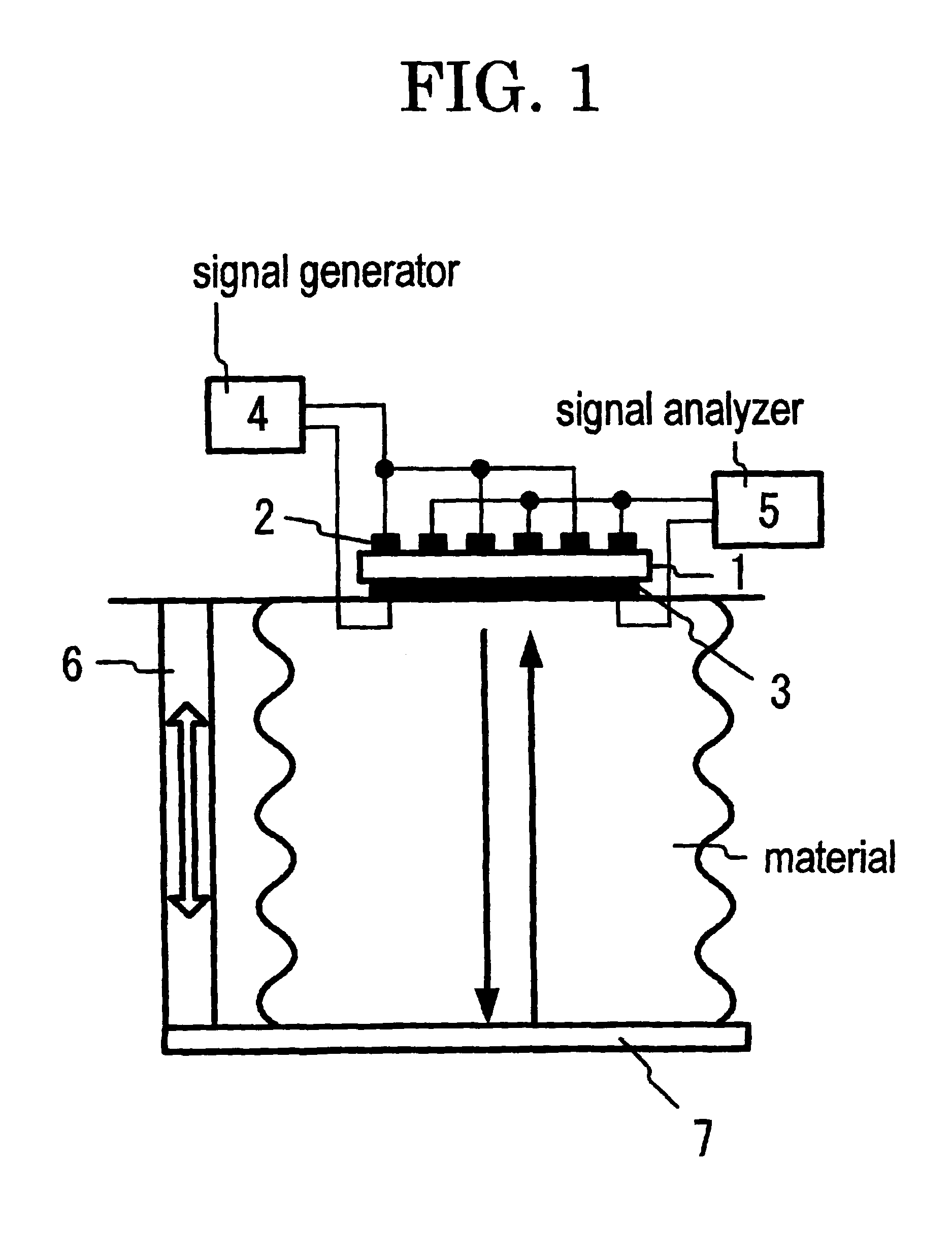
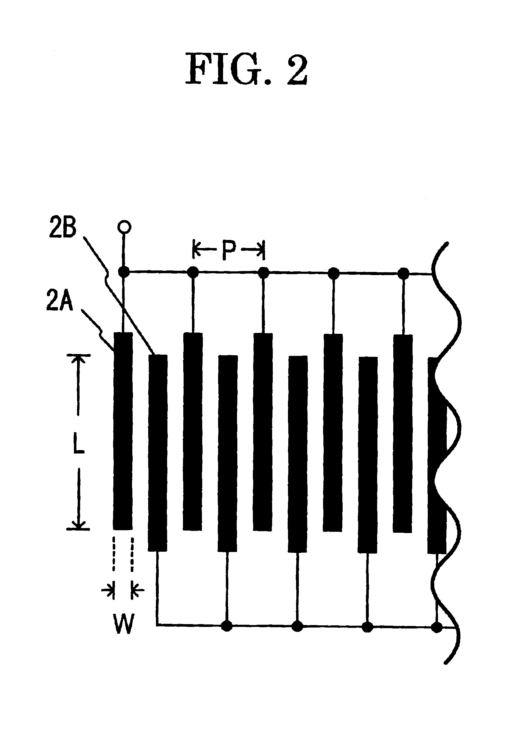
FIG. 1 shows a schematic illustration of a device for measuring sound velocity in material according to the present invention. The device for measuring sound velocity in material comprises piezoelectric substrate 1, interdigital arrangement 2 of two comb-shaped electrodes (2A and 2B), counter electrode 3, signal generator 4, signal analyzer 5, distance adjusting system 6, and reflector 7. Piezoelectric substrate 1 is made of a piezoelectric ceramic plate with a thickness (T) of 500 .mu.m, and the polarization axis thereof is parallel to the thickness direction thereof. Interdigital arrangement 2, made of an aluminum thin film, is formed on an upper end surface of piezoelectric substrate 1. Counter electrode 3, made of an aluminum thin film, is formed on a lower end surface of piezoelectric substrate 1, and in contact with a surface-part of a material. Reflector 7 is arranged to be parallel with the lower end surface of piezoelectric substrate 1, and in contact with the opposite surf...
second embodiment
FIG. 6 shows a schematic illustration of a device for measuring sound velocity in material according to the present invention. The device for measuring sound velocity in material comprises first piezoelectric substrate 8, first interdigital arrangement 9 of two comb-shaped electrodes (9A and 9B), second piezoelectric substrate 10, second interdigital arrangement 11 of two comb-shaped electrodes (11A and 11B), silicone rubber 12, counter electrode 3, signal generator 4, signal analyzer 5, distance adjusting system 6, and reflector 7. Second interdigital arrangement 11 is formed on the upper end surface of second piezoelectric substrate 10. Counter electrode 3 is cemented between first piezoelectric substrate 8 and second piezoelectric substrate 10, which are made of the same materials as piezoelectric substrate 1, and have the same sizes as piezoelectric substrate 1. First interdigital arrangement 9 is formed on a lower end surface of first piezoelectric substrate 8. The lower end su...
third embodiment
FIG. 10 shows a schematic illustration of a device for measuring sound velocity in material according to the present invention. The device for measuring sound velocity in material has the same construction as FIG. 6 except for the use of first interdigital arrangement 13 of two comb-shaped electrodes (13A and 13B) and second interdigital arrangement 14 of two comb-shaped electrodes (14A and 14B) in place of first interdigital arrangement 9 and second interdigital arrangement 11, respectively.
FIG. 11 shows a schematic illustration of first interdigital arrangement 13 composed of first comb-shaped electrode 13A and second comb-shaped electrode 13B, and second interdigital arrangement 14 composed of first comb-shaped electrode 14A and second comb-shaped electrode 14B in the device for measuring sound velocity in material in FIG. 10. The finger direction of first interdigital arrangement 13 is orthogonal to that of second interdigital arrangement 14. First interdigital arrangement 13, m...
PUM
| Property | Measurement | Unit |
|---|---|---|
| thickness | aaaaa | aaaaa |
| width | aaaaa | aaaaa |
| width | aaaaa | aaaaa |
Abstract
Description
Claims
Application Information
 - R&D
- Intellectual Property
- Life Sciences
- Materials
- Tech Scout
- Unparalleled Data Quality
- Higher Quality Content
- 60% Fewer Hallucinations
Browse by: Latest US Patents, China's latest patents, Technical Efficacy Thesaurus, Application Domain, Technology Topic, Popular Technical Reports.
© 2025 PatSnap. All rights reserved.Legal|Privacy policy|Modern Slavery Act Transparency Statement|Sitemap|About US| Contact US: help@patsnap.com


