
Piggyback monitor

Inactive Publication Date: 2002-09-12
EDTECH
View PDF8 Cites 15 Cited by
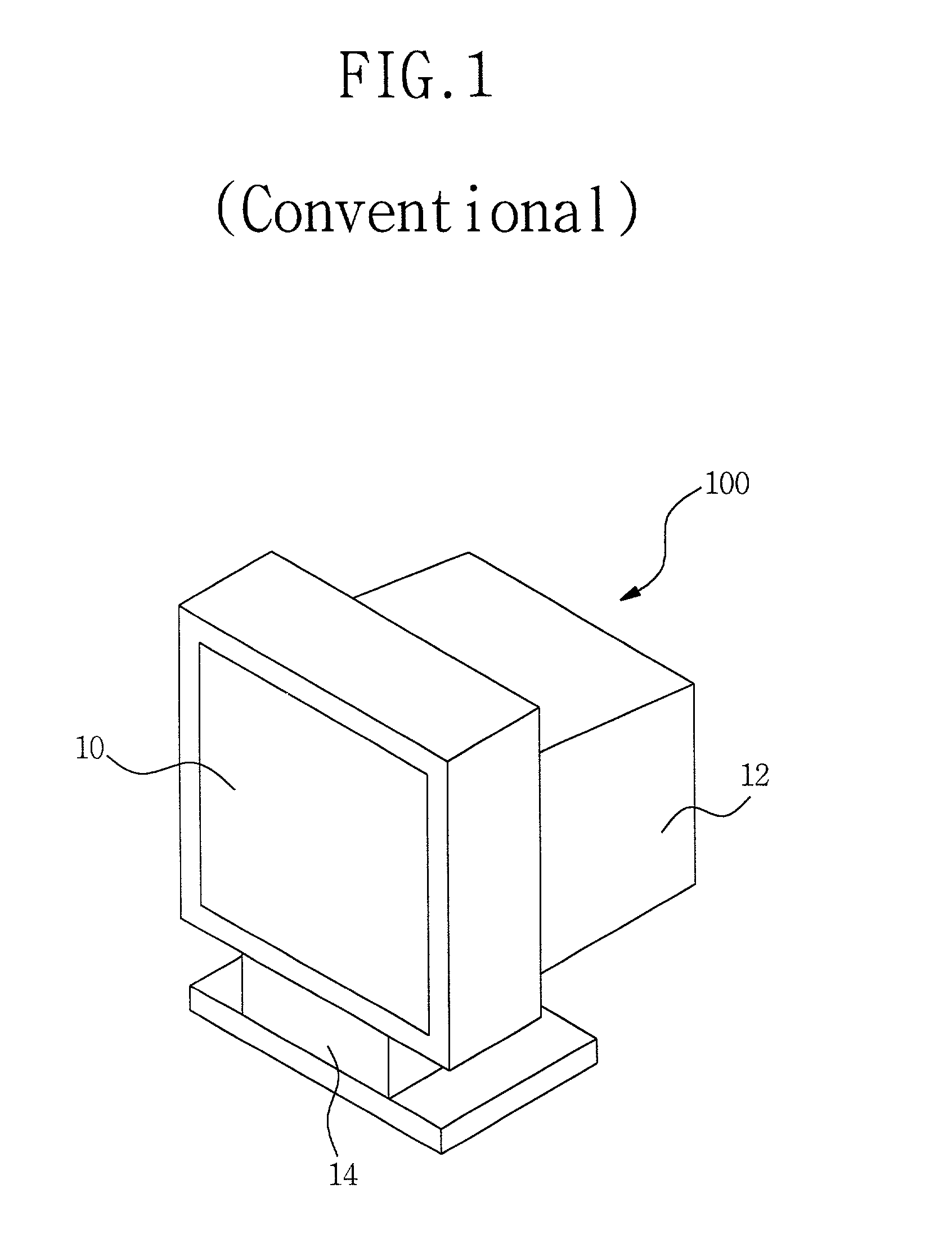
  • Summary
  • Abstract
  • Description
  • Claims
  • Application Information

AI Technical Summary

Benefits of technology

[0010] Accordingly, the present invention has been made in an effort to solve the problems occurring in the related art, and it is an object of the present invention to provide a piggyback monitor, which enables a single digital screen system to be connected with multi-systems, so that the systems can be conveniently used according to necessity and the space for the systems can be utilized as efficiently as possible.

Problems solved by technology

Further, even in the case where the thin monitor as described above is used, the volume of a personal computer (PC) is still large.
Moreover, for the digital TV (D-TV), only the screen is changed from analog to digital, and the system is not changed, so that there is a difficulty in interconnecting the systems including the D-TV, a digital versatile disc (DVD), a set-top box, etc.
As described above, in the prior art, even in the case where the monitor is thin, the systems such as the PC, the D-TV, the DVD, and the set-top box are large, and it is difficult and complicated to connect the systems with each other.

Method used


Image

  • Piggyback monitor
  • Piggyback monitor
  • Piggyback monitor

Examples


Embodiment Construction

[0019] The above and other objects, characteristics, and advantages of the present invention will be apparent from the following description along with the accompanying drawings.

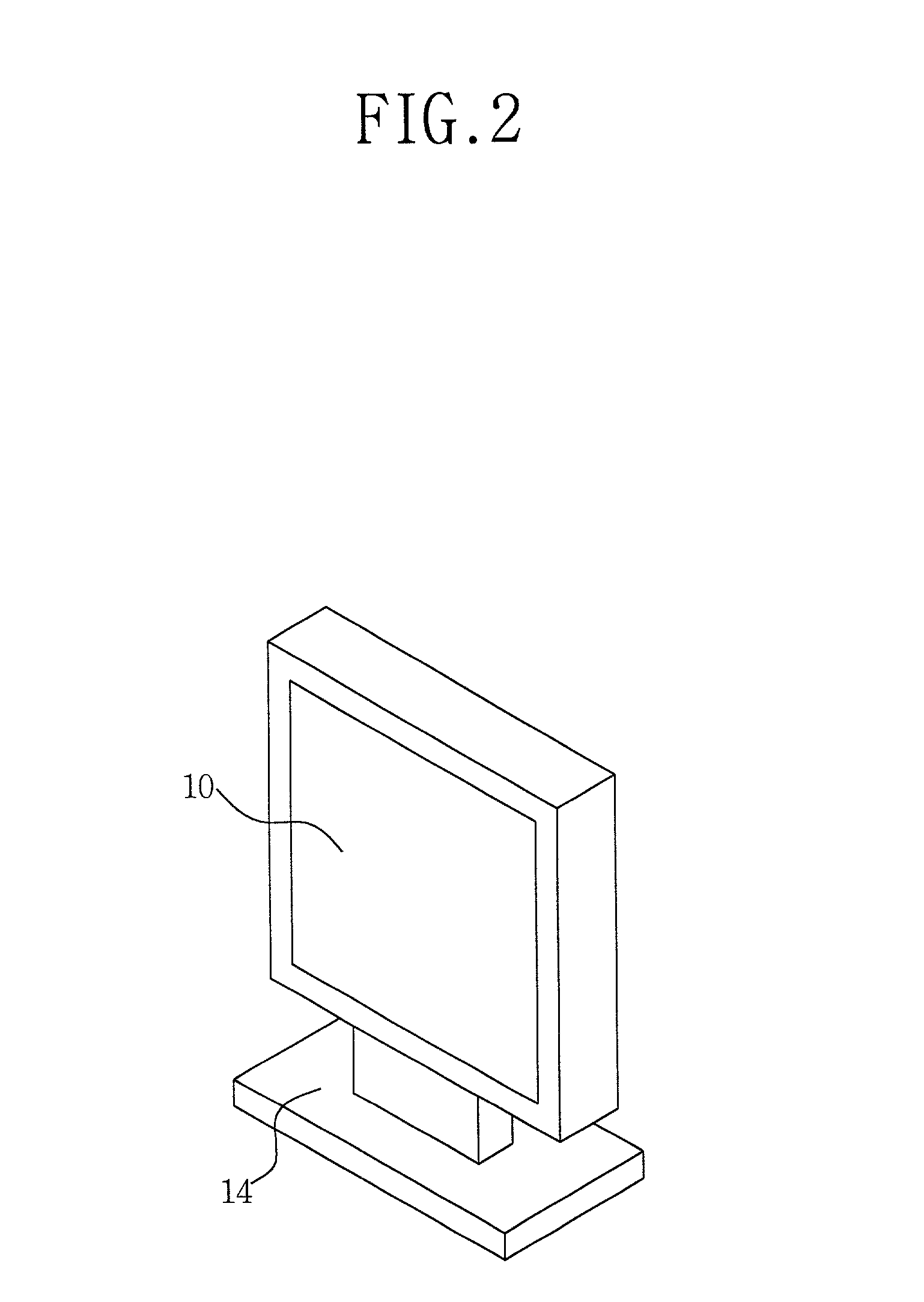
[0020] The piggyback monitor of the present invention includes connectors 32, 34, and 36 provided at the back of the monitor 10, to be connected with systems 16, 18, 20, 22, and 24, links 30 provided at the side and the back of the monitor 10, to fix the systems 16, 18, 20, 22, and 24, and a stand 14 for supporting and controlling the monitor 10 and the systems 16, 18, 20, 22, and 24.

[0021] The links 30 are provided at the upper and the lower, and the left and the right edges of the back and the side of the monitor 10.

[0022] As the systems 16, 18, 20, 22, and 24, a PC 16, a DVD 18, a D-TV 20, a set-top box 22, and a mobile phone may be employed.

[0023] The systems 16, 18, 20, 22, and 24 can be assembled with and detached from the monitor 10.

[0024] FIG. 2 is a perspective view of a TFT-LCD monitor employed in ...


PUM


Abstract

Disclosed is a piggyback monitor, to which various systems according to necessity can be mounted, so that the monitor with the systems can be conveniently used even in a narrow space. The piggyback monitor has connectors provided at a back of a monitor, to be connected with systems; links provided at a side and the back of the monitor, to fix a plurality of systems; and a stand for supporting and controlling the monitor and the systems. By the piggyback monitor, a plurality of systems can be assembled and connected with each other to be used as a single system, so that their entire volume and weight are decreased. Consequently, the assembled systems can be easily moved and installed in any space. Moreover, the systems can be connected with each other only through connectors without a cable, so that noise due to the cable and a problem of a complicated layout of the cable can be eliminated.

Description

BACKGROUND OF THE INVENTION[0001] 1. Field of the Invention[0002] The present invention relates to a digital flat panel monitor, and more particularly to a piggyback monitor, to which various systems according to necessity can be mounted, so that the monitor with the systems can be conveniently used even in a narrow space.[0003] 2. Description of the Related Art[0004] FIG. 1 is a perspective view of a conventional cathode ray tube (CRT) monitor, which will be described hereinafter.[0005] The CRT monitor 100 includes a CRT 10, a monitor body 12 provided at the back of the CRT 10, and a stand 14 for supporting the monitor body 12 and the CRT 10.[0006] The CRT monitor is of an analog type and has a shape, which is large and protrudes backward due to an electron gun for forming a screen.[0007] Recently, the monitor shows a tendency to be thinner and to consume less electric power, according to an advent of a monitor utilizing a digital flat panel such as a thin film transistor-liquid cr...

Claims


Application Information

Patent Timeline
IPC IPC(8): G06F1/16H04N5/64
CPCG06F1/16G06F1/1607G06F2200/1631H04N5/64
Inventor LIM, CHUL-HOLIM, SOO-YEN
Owner EDTECH
Learn More