
An optical disk and optical disk apparatus with tracks and grooves

Inactive Publication Date: 2002-09-12
PANASONIC CORP
View PDF0 Cites 23 Cited by
  • Summary
  • Abstract
  • Description
  • Claims
  • Application Information

AI Technical Summary

Benefits of technology

[0036] Thus, the invention described herein makes possible the advantages of (1) providing an optical disk having a pit array which is used to ensure that a converged light beam accurately follows a track center; and (2) providing an optical disk apparatus capable of ensuring that a converged light beam accurately follows a track center.

Problems solved by technology

However, a conventional SS-L / GFMT disk and a conventional optical disk apparatus for reproducing and / or recording information on a conventional SS-L / GFMT disk have the following problems.
Accordingly, there is a problem in that under the presence of an optical disk tilt of about 1.0 degrees, an off-tracking of about 0.104 .mu.m may result even if the tracking servo functions successfully.

Method used


Image

  • An optical disk and optical disk apparatus with tracks and grooves
  • An optical disk and optical disk apparatus with tracks and grooves
  • An optical disk and optical disk apparatus with tracks and grooves

Examples


Embodiment Construction

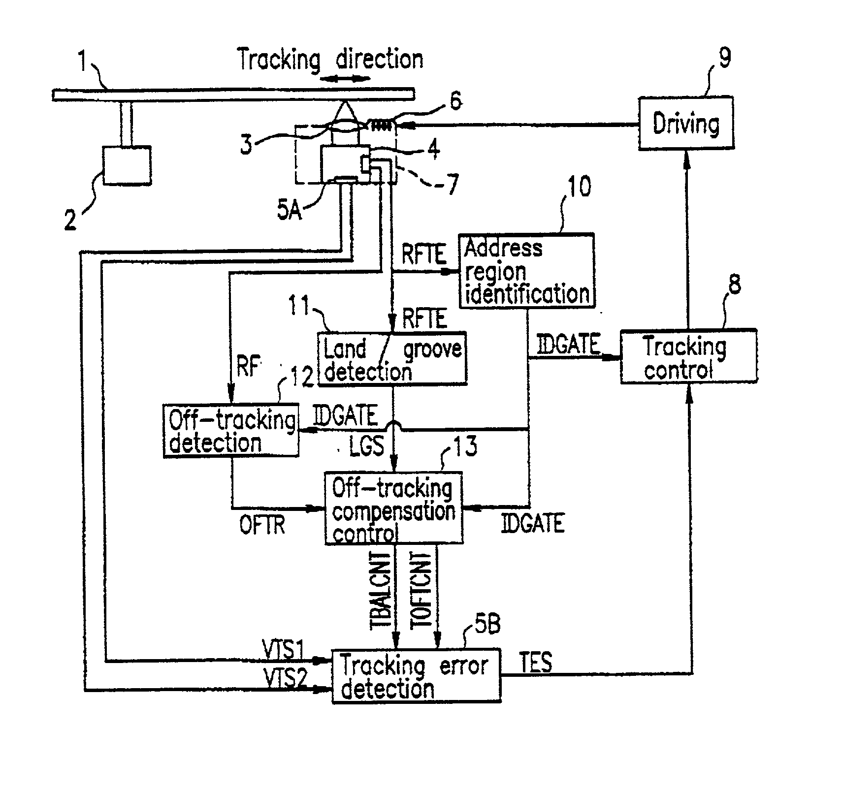
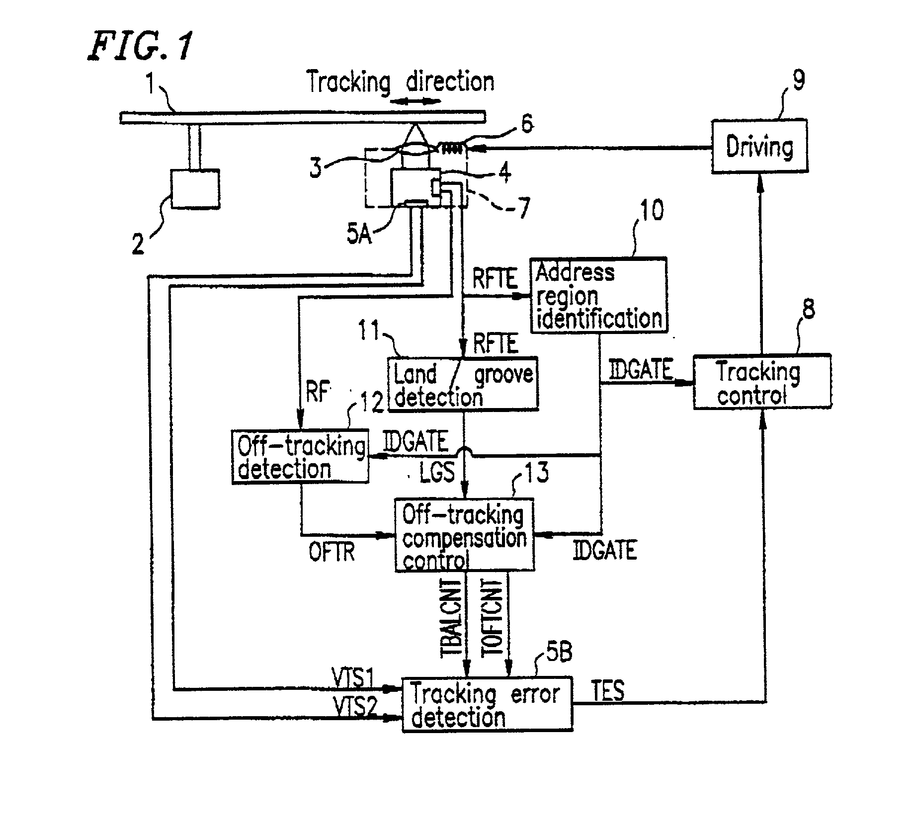
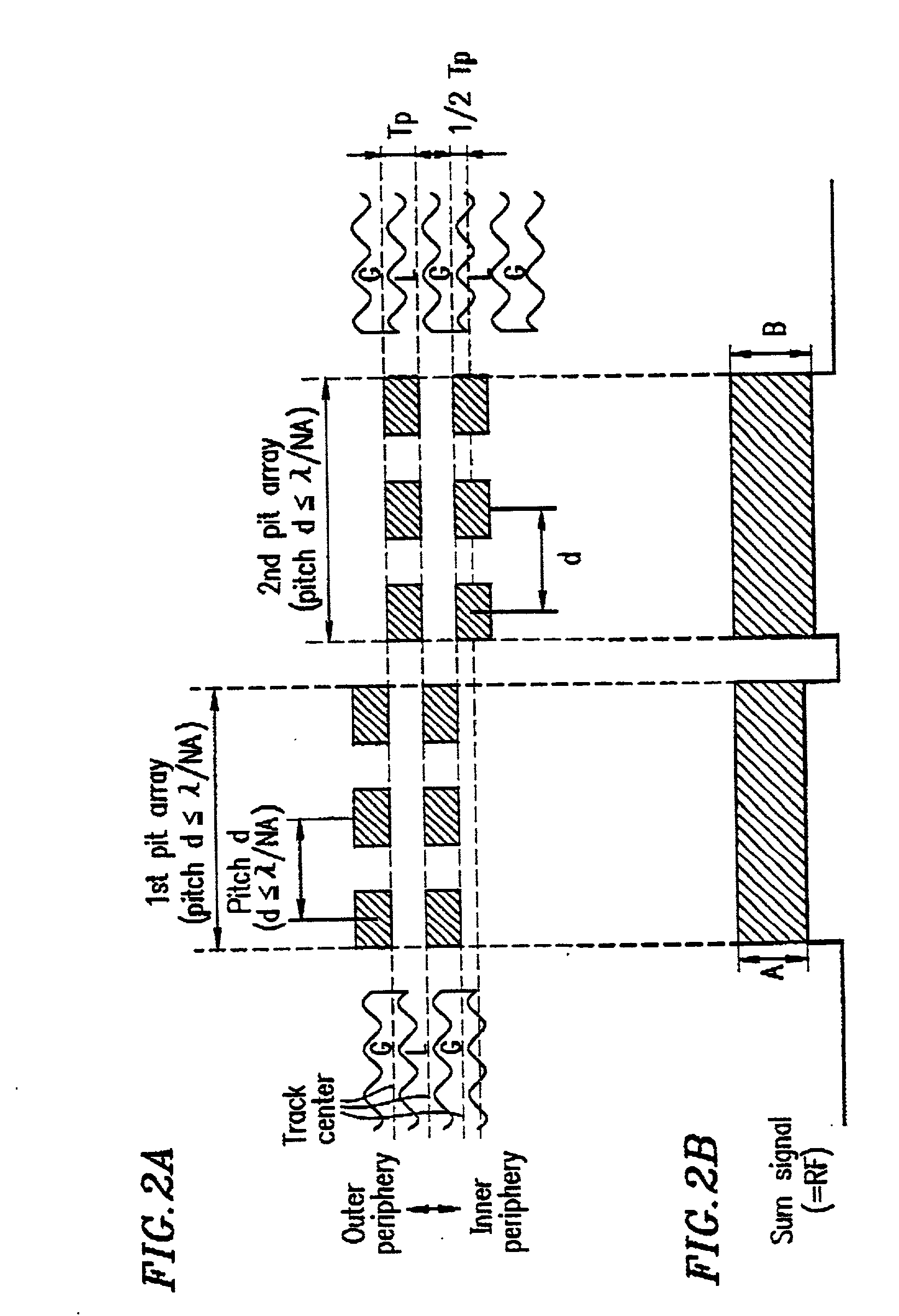
[0070] An optical disk according to the present invention includes tracks and grooves, where some of the tracks are defined by the grooves, in such a manner that the grooves are formed with a pitch equal to or greater than about .lambda. / NA. A first array of pits are provided at a position which is shifted by a predetermined radial amount with respect to each track in one of two directions substantially perpendicular to the tracks. The first array of pits are formed with a predetermined pitch along the circumferential direction, where the predetermined pitch is a function of the pitch of the grooves taking a value within a range from about 0 to about .lambda. / NA. A second array of pits are provided at a position which is shifted by a predetermined radial amount with respect to the track in the other direction which is substantially perpendicular to the tracks. The second array of pits are formed with a predetermined pitch along the circumferential direction, where the predetermined ...


PUM


Abstract

An optical disk includes tracks and grooves, the grooves being formed with a pitch equal to or greater than about .lambda. / NA. A first array of pits is provided at a position which is shifted by a predetermined amount with respect to each track in one of two directions substantially perpendicular to the tracks, the first array of pits being formed with a predetermined pitch, where the predetermined pitch is a function of a pitch of the grooves taking a value within a range from about 0 to about .lambda. / NA. A second array of pits is provided at a position which is shifted by a predetermined amount with respect to the track in the other one of the two directions substantially perpendicular to the tracks, the second array of pits being formed with a predetermined pitch, where the predetermined pitch is a function of the pitch of the grooves taking a value within the range from about 0 to about .lambda. / NA. .lambda. is a wavelength of a light beam which is radiated on the optical disk, and NA to a numerical aperture of a lens.

Description

BACKGROUND OF THE INVENTION[0001] 1. Field of the Invention[0002] The present invention relates to an optical disk and to an optical disk apparatus which is capable of detecting off-tracking based on a reproduction signal from the optical disk and compensating for the off-tracking.[0003] 2. Description of the Related Art[0004] Optical disks such as compact optical disks (CDs) and digital video (or versatile) disks (DVDs) are used as information recording media for recording data, images, and / or sounds, and are widely utilized in OA (office automation) apparatuses, AV (audio visual) apparatuses, and the like. In the field of large-capacity rewritable optical disks, one attempt to realize increased surface capacity has been to allow information to be recorded in both "grooves" (i.e., concave portions formed by guide grooves of spiral tracks) and "lands" (i.e., interspaces between "grooves") so that the information recorded in the grooves and lands can be reproduced.[0005] There is a c...

Claims


Application Information

Patent Timeline
IPC IPC(8): G11B7/007G11B7/013G11B7/09G11B7/24085G11B27/19G11B27/30
CPCG11B7/007G11B7/00718G11B7/00745G11B7/0901G11B7/0938G11B7/24085G11B27/19G11B27/3027G11B7/2407G11B7/095
Inventor TAKAMINE, KOUICHIYAMADA, SHIN-ICHIISHIDA, TAKASHINAKAMURA, ATSUSHINISHIWAKI, SEIJI
Owner PANASONIC CORP
Learn More