Image reproduction apparatus, image processing apparatus, and method therefor

a technology of image processing and image information, applied in the direction of television systems, instruments, navigation instruments, etc., can solve the problems of wasteful processing of other portions, inefficient processing of other parts, and limited technology in the correctness, precision, etc. of a model, so as to improve real-time reproducibility and efficient reproduction of stored image information

Inactive Publication Date: 2002-09-12
CANON KK
View PDF8 Cites 27 Cited by
  • Summary
  • Abstract
  • Description
  • Claims
  • Application Information

AI Technical Summary

Benefits of technology

[0009] The present invention has been developed to solve the above mentioned problems, and aims at efficiently reproducing stored image information when virtual space is designed in a walk-through system using the IBR technology, and improving real-time reproducibility.

Problems solved by technology

However, the technology is limited in correctness, precision, reality, etc. of a model.
Although the other portions are not used, it is necessary to read data or perform a decoding process on the entire panoramic image, thereby performing an inefficient process.
Although the reading and decoding processes are performed on the entire panoramic image, only a part of it is practically used for display, and other portions are wastefully processed.
Especially when a full round image or a full sky image is used as a panoramic image, most of the processes of reading and decoding the panoramic image at each viewpoint position are not required and wasteful when the image is actually displayed.
That is, the computer is excessively loaded, thereby disabling the walk-through system in reproducing and displaying images in real time.

Method used


Image

  • Image reproduction apparatus, image processing apparatus, and method therefor
  • Image reproduction apparatus, image processing apparatus, and method therefor
  • Image reproduction apparatus, image processing apparatus, and method therefor

Examples


first embodiment

[0036] [First Embodiment]

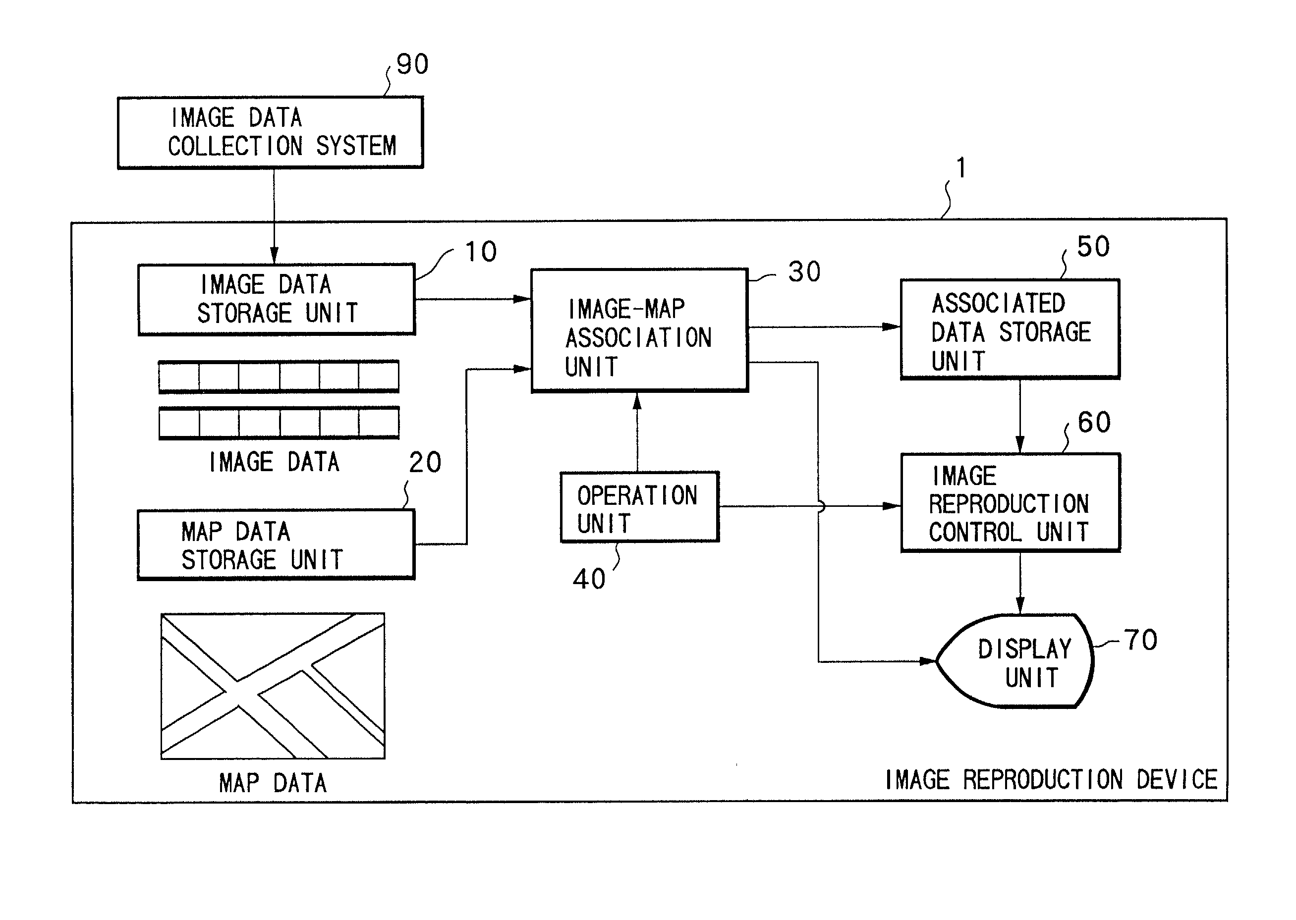
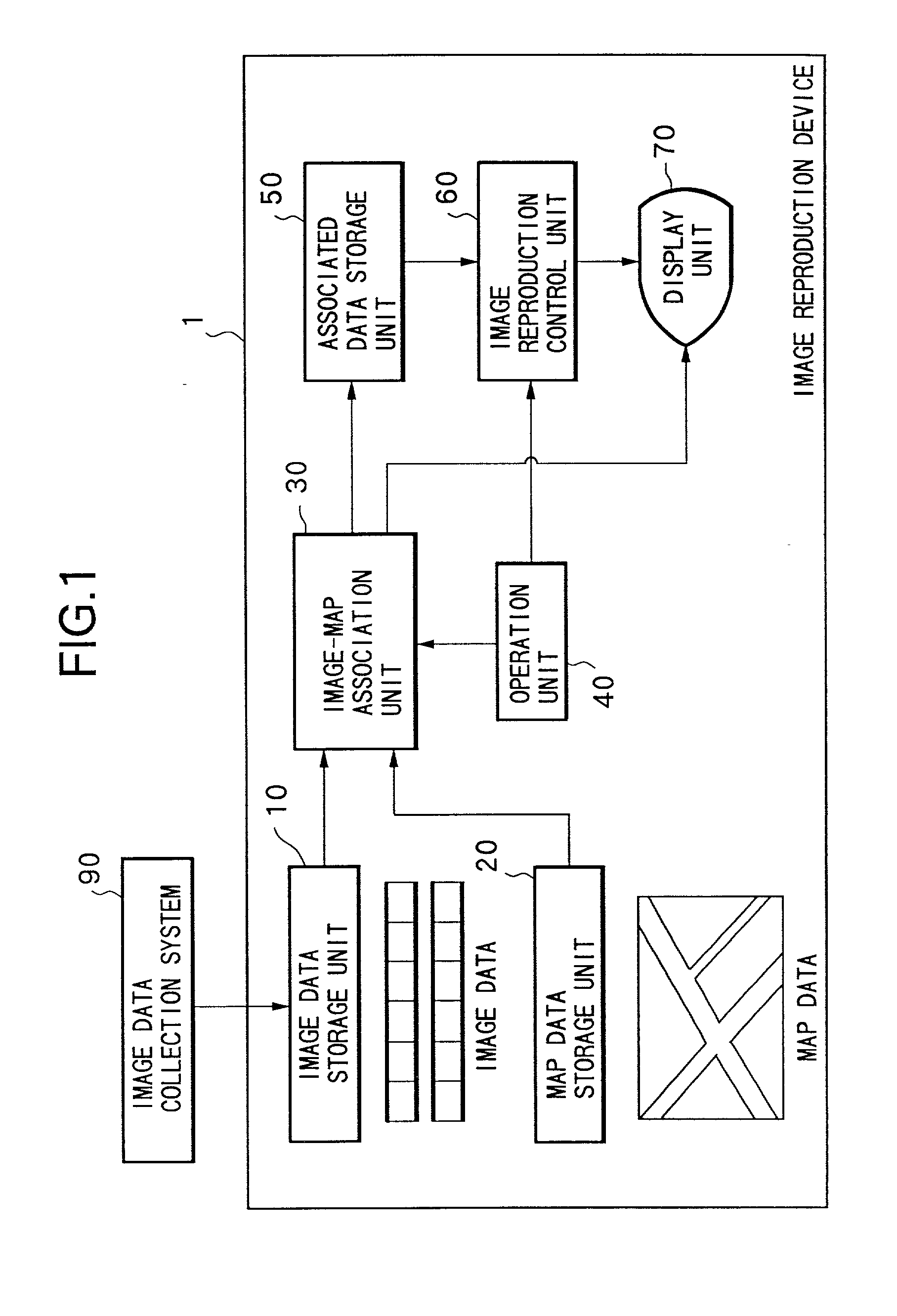
[0037] Described first is a walk-through system of virtual space according to the present embodiment. According to the present embodiment, panoramic image data is generated from captured image data obtained by a plurality of capture devices mounted on a moving object such as a vehicle, etc., and the panoramic image data is stored after associated with the map data indicating the position in the real space. Then, depending on the position and the direction of the viewpoint of the user in the virtual space, a display image is produced from the stored panoramic image data, thereby realizing walk-through in the virtual space.

[0038] FIG. 1 is a block diagram of the configuration showing the function of the walk-through system according to the present embodiment. The walk-through system comprises the image data collection system 90 and the image reproduction device 1. The image reproduction device 1 comprises the image data storage unit 10, a map data storage unit...

second embodiment

[0073] [Second Embodiment]

[0074] According the above mentioned first embodiment, a panoramic image is divided into a plurality of partial images and stored. However, each of the partial images can share an overlapping area with each other.

[0075] FIGS. 15A and 15B show the range of the field of view of a partial image according to the second embodiment. The partial images 221 to 226 shown in FIG. 11 have the field of view of 60.degree. equal to that of the display image. On the other hand, as shown in FIG. 15A, each partial image has a field of view larger than 60.degree., which equals the field of view of the display image, and shares an overlapping portion with an adjacent partial image. The hatched portion of each partial image is the portion beyond the 60.degree. range of the image indicating the overlapping portion shared with the adjacent partial image.

[0076] By having an overlapping portion as described above, a high quality combined image can be obtained in step S125. That is...

third embodiment

[0078] [Third Embodiment]

[0079] According to each of the above mentioned embodiments, it is necessary to read one or more files for each position of a viewpoint because the data of one partial image is stored in a file. Since it takes some time to access (retrieve) a file, it is better reduce the file reading process. That is, a process can be performed at a higher speed by reducing the number of times of the file reading processes as well as reducing the amount of data to be decoded using partial images. Therefore, according to the third embodiment, a file contains a plurality of partial images to further raise the processing speed by reducing the number of times of file accessing processes as well as by dividing a panoramic image for storage.

[0080] In the following explanation, each of n panoramic images is divided into m partial images, and is stored in a file. Therefore, one file stores m.times.n partial images. FIG. 16 shows an example of storing data in a file according to the...


PUM


Abstract

Each of the panoramic images corresponding to a plurality of positions of a viewpoint is compressed and stored as partial images obtained by dividing each panoramic image by a predetermined field of view. The panoramic image has a field of view wider than a display field of view of an image to be displayed on a display unit. A partial image containing an image to be reproduced is selected based on the information about the position and the direction of a viewpoint and the display field of view, and an image corresponding to the position and the direction of a viewpoint is generated and displayed from the selected partial image. Thus, when virtual space in the walk-through system is designed using the IBR technology, stored image data can be efficiently reproduced.

Description

FIELD OF THE INVENTION[0001] The present invention relates to an image reproduction apparatus, an image processing apparatus, and a method for processing image data obtained by capturing an image in real space, and presenting the virtual space.BACKGROUND OF THE INVENTION[0002] Technology of capturing real space using a capture device mounted on a moving object, and representing the captured real space as virtual space using a computer based on the captured image data (for example, `Building Image-Based Cybercities by Using Vehicle-Mounted Cameras` by Endoh, Katayama, Tamura, Hirose, Watanabe, and Tanigawa (published by Shingaku Society, PA-3-4, pp.276-277, in 1997), `Building Image-Based Cybercities by Using Vehicle-Mounted Cameras (2)--Generation of Wide-Range Virtual Environment by Using Photorealistic Images--` by Hirose, Watanabe, Tanigawa, Endoh, Katayama, and Tamura (published in Proceedings of the Virtual Reality Society of Japan Second Annual Conference, pp.67-70, in 1997), ...

Claims


Application Information

Patent Timeline
Patent Type & Authority Applications(United States)
IPC IPC(8): G09B29/00G01C21/00G01C21/26G06T1/00G06T3/00G06T19/00G08G1/0969G09B29/10H04N5/76
CPCG06T15/205
Inventor KOTAKE, DAISUKEKATAYAMA, AKIHIRO
Owner CANON KK
Why Eureka
Try Eureka