Machine tool

a technology of machine tools and parts, applied in the field of machine tools, to achieve the effect of low manufacturing cost, easy assembly, and free of guide backlash

Inactive Publication Date: 2002-09-12
HULLER HILLE
View PDF8 Cites 5 Cited by
  • Summary
  • Abstract
  • Description
  • Claims
  • Application Information

AI Technical Summary

Benefits of technology

0007] It is an object of the present invention to embody a machine tool which comprises an x skid and a y skid displaceably arranged thereon, with the latter carrying a tool spindle, and the skids of which can be manufactured at a low manufacturing expense and then easily be assembled, and which are free of any guide backlash irrespective of the wear of the guides.

Problems solved by technology

Even when a backlash occurs due to wear of the guides, the guides can normally still be used while they have to be replaced in the conventional construction of the prior art.

Method used


Image

  • Machine tool
  • Machine tool
  • Machine tool

Examples


Embodiment Construction

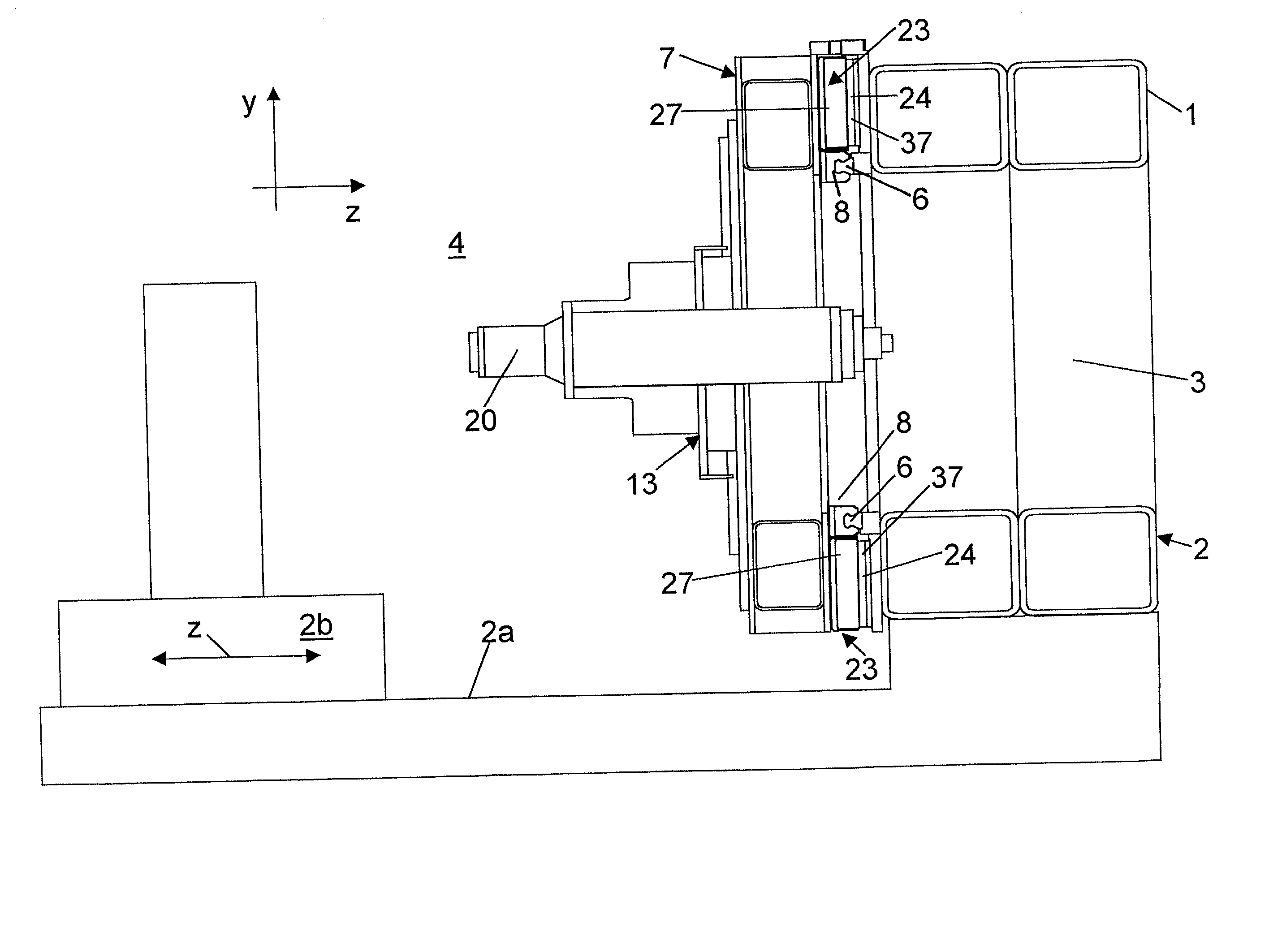
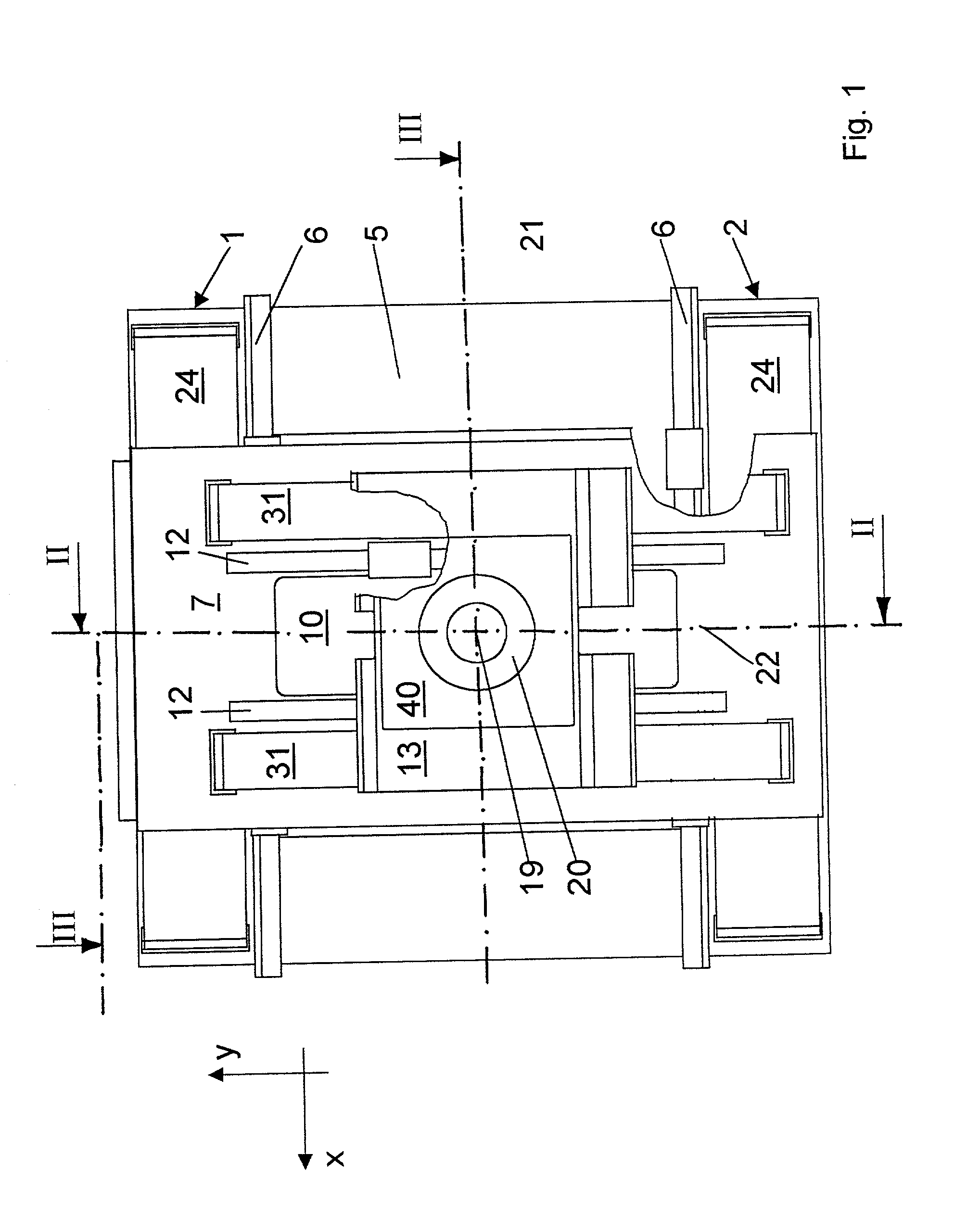
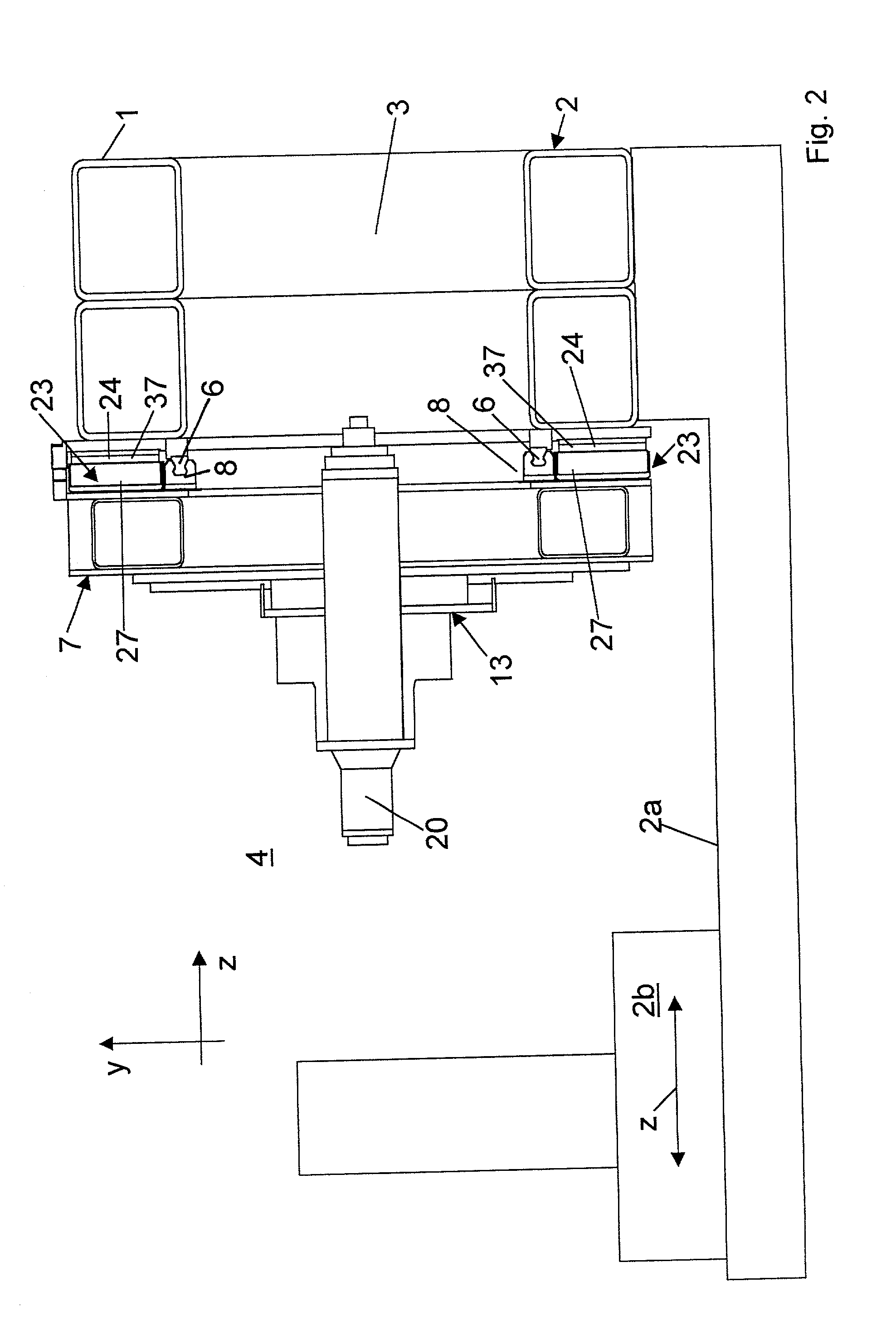
[0026] As can be seen especially clearly in FIGS. 1 through 3, the machine tool illustrated in the drawing comprises a rack 2 formed as a frame 1 of approximately square shape when viewed in the horizontal z direction. The rack 2 is supported by a base frame 2a. As can be seen in FIGS. 2 and 3, the frame 1 consists of hollow sections and encloses an inner space 3 which is open to both sides, especially towards the operating side 4. On the operating side 4, a work piece carrier 2b is supported by the base frame 2a, which carrier may be displaceable in z direction in the usual manner.

[0027] On the front side 5 of the rack 2 facing the operating side 4, a guide rail 6 is mounted on each side of the inner space 3 in a vertical x-y plane and extending in x direction, respectively, with the guide rails 6 being arranged parallel to each other. An x skid 7 having guide shoes 8 and being horizontally displaceable in x direction rests on the guide rails 6. The guide shoes 8 are attached to th...


PUM

PropertyMeasurementUnit
displacementaaaaaaaaaa
forcesaaaaaaaaaa
forceaaaaaaaaaa

Abstract

A machine tool comprises a rack, a horizontally displaceable x skid and a y skid that is vertically displaceable thereon. The skids are drivable by linear motors which are arranged on the front side of the rack and the face side of the x skid, respectively, and on the rear side of the x skid and the rear side of the y skid, respectively. The same may apply to the x guides and the y guides. The air gaps of the linear motors of each skid are arranged in one plane.

Description

BACKGROUND OF THE INVENTION[0001] 1. Field of the Invention[0002] The present invention is related to a machine tool.[0003] 2. Background Art[0004] A machine tool comprising a frame-like machine rack in which an x skid runs horizontally displaceable on guides is known from EP 0 742 072. Inside the x skid, another y skid runs vertically displaceable on guides. For actuation, x linear motors and y linear motors are provided which are arranged with their sides facing each other so that the forces of the x linear motors acting in y direction and the forces of the y linear motors acting in x direction cancel each other out, providing a symmetry of forces. The same applies to the drives of a z skid which carries a tool spindle and which rests on the y skid. This so-called box-in-box construction is widely used because of the compact and rigid framework construction and the symmetry of forces. As a disadvantage, the working of the skids and the assembly and, if necessary, maintenance work ...

Claims


Application Information

Patent Timeline
Patent Type & Authority Applications(United States)
IPC IPC(8): B23Q1/62B23Q5/28B23Q5/34
CPCB23Q1/623B23Q5/28B23Q5/34Y10T409/307112Y10T409/309576Y10T408/91
Inventor STENGELE, GERALDGEIGER, DIETRICH
Owner HULLER HILLE
Why Eureka
Try Eureka