Endoscope

a technology of endoscope and endoscope, which is applied in the field of endoscope, can solve the problems of complex sterilization process, high toxicity of gaseous disinfectants, and inability to use endoscopes immediately after sterilization process

Inactive Publication Date: 2002-09-12
OLYMPUS CORP
View PDF0 Cites 56 Cited by
  • Summary
  • Abstract
  • Description
  • Claims
  • Application Information

AI Technical Summary

Benefits of technology

0016] Accordingly, it is an object of the present invention to provide an endoscope with a small diameter distal end wherein the endos...

Problems solved by technology

As is well known, gaseous disinfectants are highly toxic, and a sterilization process becomes complex to assure safety of humans.
Since aeration to evacuate gas residing on an instrument subsequent to the sterilization process takes time, the endoscope cannot be used immediately after the sterilization process.
Furthermore, adverse effects of the gas to the environment become a concern.
The running cost involved in the sterilization process is high.
The management of the antiseptic solutions is typically complicated, and a great deal of cost is required to dispose the used antiseptic solutions.
However, high-pressure vapor typically penetrates almost all polymeric materials (resin, rubber, resin adhesives, etc).
The epoxy resin under a direct attack by the high-pressure vapor de...

Method used


Image

  • Endoscope
  • Endoscope
  • Endoscope

Examples


first embodiment

[0037] the present invention will now be discussed, referring to FIGS. 1 through 4.

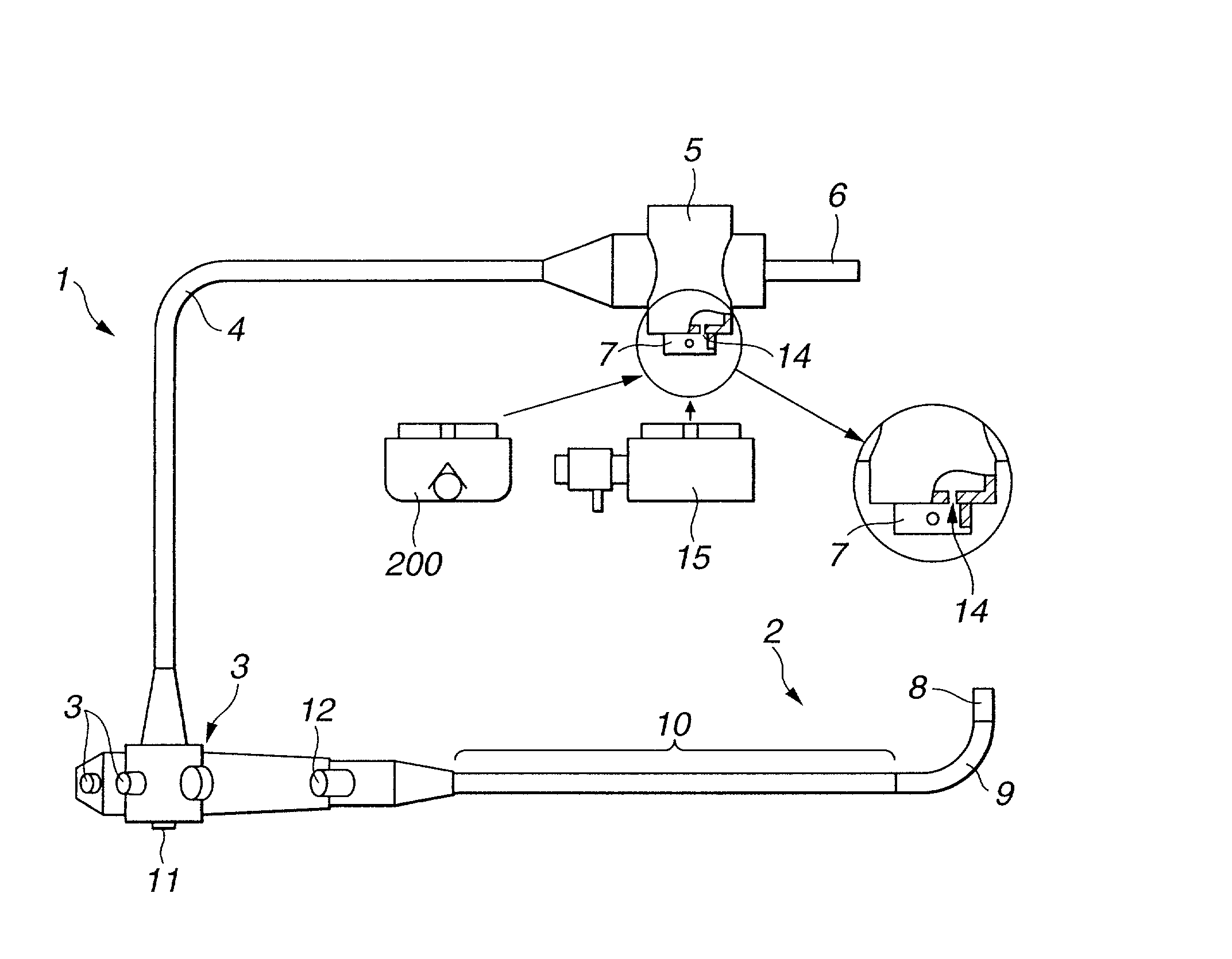
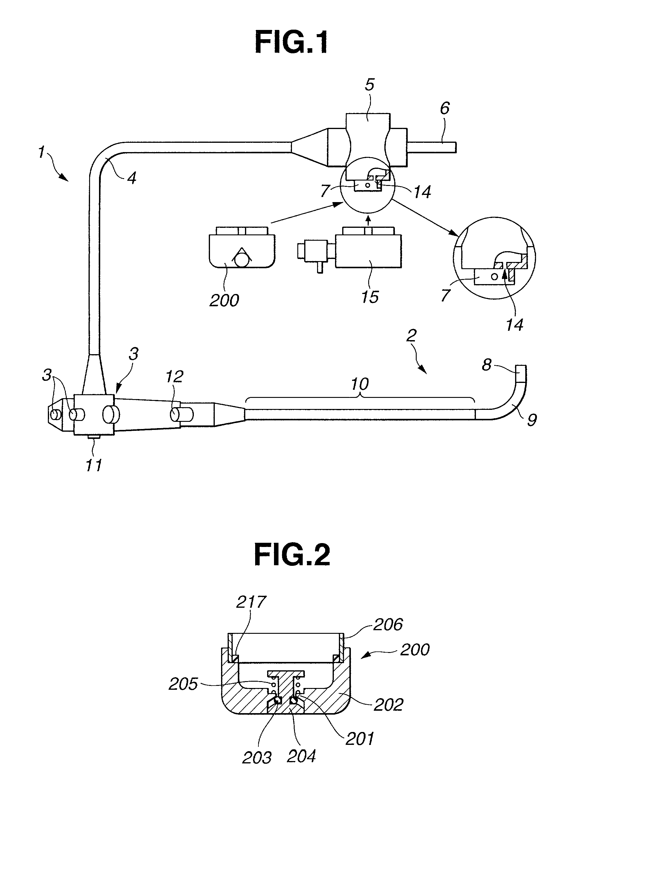
[0038] FIG. 1 is a diagram illustrating the construction of an electronic endoscope 1 of the present invention. FIG. 2 is a cross-sectional view illustrating a check valve cap. FIG. 3 is a longitudinal sectional view of a distal portion of the electronic endoscope 1 of the present invention.

[0039] Referring to FIG. 1, the electronic endoscope 1 of this embodiment includes an insert section 2 having a CCD (Charge-Coupled Device) in a distal portion thereof as a solid-state image pickup device, a control section 3 which is connected to a proximal end of the insert section 2 and gripped by an observer to perform a variety of operations, and a universal cord 4 extending from the control section 3. A connector section 5 is attached to the other end of the universal cord 4. The connector section 5 is connected to an optical device (not shown) and a camera control unit (hereinafter referred to as "CCU") (not...

eighth embodiment

[0157] the present invention is discussed below.

[0158] The eighth embodiment is identical to each the third through seventh modifications with a portion thereof modified, and is discussed with reference to FIG. 7. The discussion that follows focuses on only the difference therebetween. The rest of the eighth embodiment remains unchanged from the third through seventh embodiments, and the discussion thereof is skipped here.

[0159] FIG. 7 is a longitudinal sectional view of an image pickup unit in accordance with the eighth embodiment of the present invention. In the eighth embodiment, a first lens barrel 72 is inserted into and fixed in the inner circumference of an image pickup barrel 77, and the two barrels 72 and 77 are laser welded for air-tightness. FIG. 7 shows a laser weld portion 73. A second lens barrel 74 housing an objective lens group is housed in the first lens barrel 72.

[0160] In this arrangement, the number of air-tight mating portions is reduced by one in comparison wi...

eleventh embodiment

[0203] the present invention is discussed below.

[0204] The eleventh embodiment is identical to the eighth embodiment with a portion thereof modified, and is discussed with reference to FIG. 16. Discussed below is a difference therebetween and the rest of the eleventh embodiment is identical to the eighth embodiment. The discussion thereof is thus skipped here.

[0205] FIG. 16 is a longitudinal sectional view of an image pickup unit in accordance with the eleventh embodiment of the present invention. The image pickup unit of the eleventh embodiment includes an image pickup barrel 151 fabricated of a metal, a second lens barrel 152 inserted into the image pickup barrel 151 within the inner circumference thereof and subjected to a black low-reflectance surface treatment process, and a first lens barrel 153 fitted over the image pickup barrel 151 around the outer circumference thereof and subjected to a pre-brazing surface treatment process. The inner circumference of the second lens barr...


PUM


Abstract

An endoscope includes a first lens barrel having a brazing surface in at least a brazing portion thereof, and supporting an optical window member brazed thereon, and a second lens barrel arranged to be proximal with respect to the optical window member and supporting optical members on the inner circumference thereof. At least a distal end surface of one of the second lens barrel, a diaphragm member, a spacer ring, and the optical members has light reflectance lower than that of the brazing surface of the first lens barrel. At least the inner circumference of the second lens barrel has a light reflectance lower than that of the brazing surface of the first lens barrel or has a reflection surface more irregular than the brazing surface of the first lens barrel.

Description

[0001] This application claims benefit of Japanese Application No. 2001-069104 filed on Mar. 12, 2001, and No. 2002-017315 filed on Jan. 25, 2002, the contents of which are incorporated by this reference.BACKGROUND OF THE INVENTION[0002] 1. Field of the Invention[0003] The present invention relates to an endoscope and, more particularly, an autoclave sterilization type endoscope.[0004] 2. Description of the Related Art[0005] Endoscopes are now widely used in the medical care field. The insert section of the endoscope is inserted into the body cavity of a human to observe a deep portion of the body, and if necessary, a medical treatment is performed using an instrument together with the endoscope.[0006] To Control communicable diseases, sterilizing and disinfecting a medical endoscope after use are an essential requirement.[0007] Gaseous disinfectants, such as ethylene oxide, or antiseptic solutions are conventionally used in a sterilization process. As is well known, gaseous disinfe...

Claims


Application Information

Patent Timeline
IPC IPC(8): G02B23/24A61B1/00A61B1/04G02B23/26
CPCA61B1/042A61B1/00096A61B1/0011A61B1/051
Inventor KIKUCHI, AKIRAHIGUMA, MASAKAZU
Owner OLYMPUS CORP
Why Eureka
Try Eureka