Anterior lumbar spacer

a spacer and anterior lumbar technology, applied in the field of two-part intervertebral spacers, can solve the problems of pain, chronic and/or debilitating back pain, and difficulty in inserting the implant into position,

Inactive Publication Date: 2002-09-12
OSTEOTECH INC
View PDF8 Cites 77 Cited by
  • Summary
  • Abstract
  • Description
  • Claims
  • Application Information

AI Technical Summary

Benefits of technology

0014] There is also disclosed a method of restoring spacing between adjacent vertebrae which consists of providing a spacer element configured to receive a locking element. The method includes initially displacing or distracting the vertebrae and inserting the spacer ring between the adjacent vertebrae such that the adjacent vertebrae bear on upper and lower surfaces of the ring. The ring may initially be provided with threads in either the inner surface of the C-shaped ring or the bore of the intact ring or may be simultaneously threaded with the formation of threads in adjacent vertebrae. Thereafter the locking element is threaded into the threads formed in the spacer ring and adjacent vertebrae to secure the spacer ring against migration and locking the implant in between the adjacent vertebrae.

Problems solved by technology

When one or more disks degenerate through trauma, spondylolisthesis or other pathologies, nerves passing near the affected area may be compressed and are consequently irritated.
The result may be chronic and / or debilitating back pain.
Common deficiencies in some of the prior art implants may include expulsion of the implant from between adjacent vertebrae, difficulty in inserting the implant into position, and / or lack of ability to allow incorporation of implant into the body.

Method used


Image

  • Anterior lumbar spacer
  • Anterior lumbar spacer
  • Anterior lumbar spacer

Examples


Embodiment Construction

[0020] Preferred embodiments of the presently disclosed anterior lumbar spacer will now be described in detail with reference to the drawings in which like reference numerals designate identical or corresponding elements in each of the several views. While the preferred use of the spacer is disclosed for use within the lumbar region of the spine, the spacer can be adapted for use within other regions of the spine such as cervical, etc.

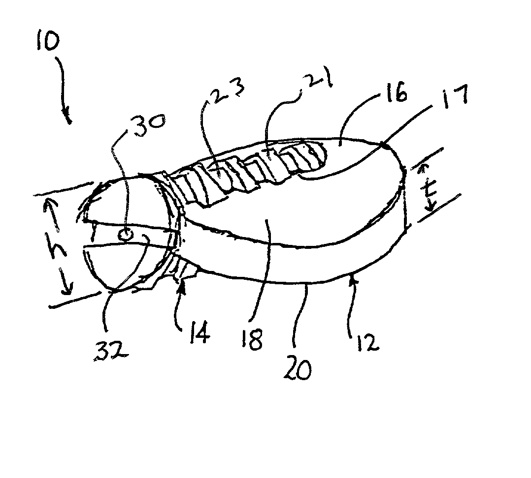
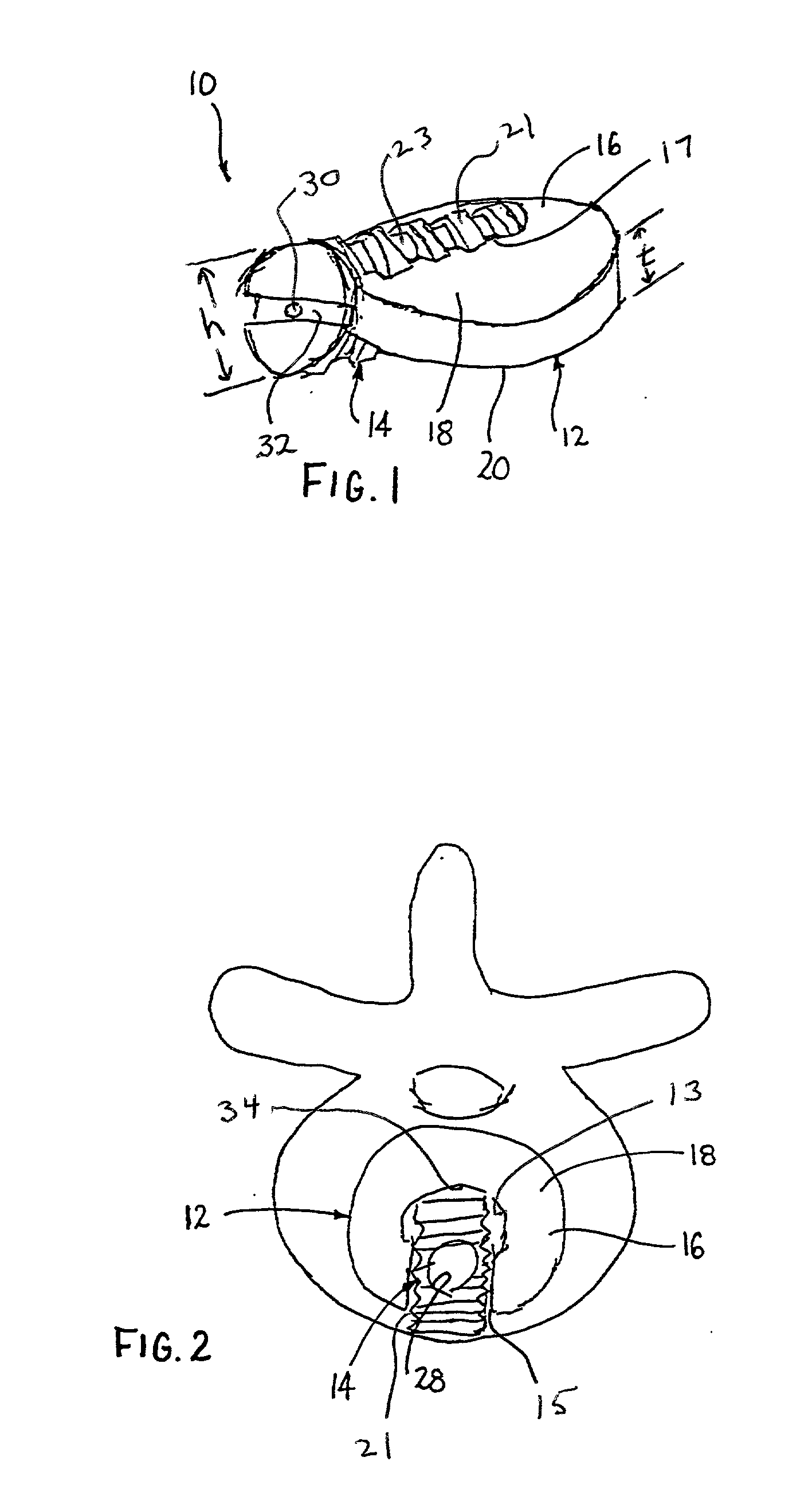
[0021] Referring to FIGS. 1 and 2, a two-part intervertebral implant 10 includes a first component or spacer ring 12 and a second component or locking implant 14 configured to prevent migration of implant 10. Spacer ring 12 and / or locking implant 14 can be made from either cortical or cancellous bone or, alternately, from any biocompatible material having the requisite strength requirements including ceramics, polymers, composites, metals such as stainless steel, titanium, etc.

[0022] In one embodiment, spacer ring 12 includes a generally C-shaped body ...


PUM


Abstract

There is provided a combined two-part intervertebral implant configured to restore the spacing between adjacent vertebrae. The implant generally includes a spacer ring having upper and lower vertebral engaging surfaces and a bore for receipt of a locking element. The implant further includes a locking element which is engagable within the spacer ring and has a diameter or height greater than the thickness of the spacer ring. In one embodiment, the spacer ring may be formed as a C-shaped element. In an alternative embodiment, the spacer ring may be formed as an intact ring having a side bore for receipt of the locking element. One or both parts of the implant may be partially or wholly surface demineralized to provide a flexible surface on implant. A method of using the spacer ring and locking element to secure the assembled implant between adjacent vertebrae is also disclosed.

Description

BACKGROUND OF THE INVENTION[0001] 1. Technical Field[0002] The present disclosure relates to an intervertebral implant for spinal fusion and, more particularly, to a two part intervertebral spacer having a large vertebral supporting surface area and structure to lock the spacer within the intervertebral space to prevent expulsion.[0003] 2. Background of Related Art[0004] The spine is a flexible column formed of a series of bone called vertebrae. The vertebrae are hollow and piled one upon the other, forming a strong hollow column for support of the cranium and trunk. The hollow core of the spine houses and protects the nerves of the spinal cord. The different vertebrae are connected together by means of articular processes and intervertebral, fibro-cartilages. In general, a vertebral body is made of a cortical shell enclosing a cancellous (spongy) bone core. The portion of the cortical bone shell facing the surface of the disk is the endplate.[0005] The intervertebral fibro-cartilag...

Claims


Application Information

Patent Timeline
Patent Type & Authority Applications(United States)
IPC IPC(8): A61B17/88A61F2/00A61F2/28A61F2/30A61F2/44A61F2/46
CPCA61F2/28A61F2/442A61F2/446A61F2/4465A61F2/4611A61F2002/2817A61F2002/2835A61F2002/2839A61F2002/30059A61F2002/30115A61F2002/30125A61F2002/30131A61F2002/30153A61F2002/30405A61F2002/30795A61F2002/30797A61F2002/3082A61F2002/3085A61F2002/30874A61F2002/4475A61F2002/4638A61F2220/0025A61F2230/0006A61F2230/0008A61F2230/0013A61F2230/0019A61F2310/00017A61F2310/00023A61F2310/00179A61F2310/00359A61F2002/30873A61F2002/30593
Inventor ALFARO, ARTHUR A.SHIMP, LAWRENCE A.BOYLE, JOHN W.GEREMAKIS, PERRYRUSSEL, JAMESSCARBOROUGH, NELSON L.
Owner OSTEOTECH INC
Why Eureka
Try Eureka