Bone hemi-lumbar interbody spinal fusion implant having an asymmetrical leading end and method of installation thereof

Inactive Publication Date: 2006-04-04
WARSAW ORTHOPEDIC INC
View PDF98 Cites 78 Cited by
  • Summary
  • Abstract
  • Description
  • Claims
  • Application Information

AI Technical Summary

Benefits of technology

[0017]The interbody spinal implant of the present invention is for placement between adjacent vertebral bodies of a human spine across the height of the disc space between those adjacent vertebral bodies. The implant preferably does not extend beyond the outer dimensions of the two vertebral bodies adjacent that disc space and preferably maximizes the area of contact of the implant with the vertebral bone. In a preferred embodiment, the implant has a leading end configured to conform to the anatomic contour of at least a portion of the anterior, posterior, or lateral aspects of the vertebral bodies depending on the intended direction of insertion of the implant, so as to not protrude beyond the curved contours thereof. The implant has an asymmetrical leading end modified to allow for enhanced implant length without the corner of the leading end protruding out of the disc space. As used herein, the phrase “asymmetrical leading end” is defined as the leading end of the implant lacking symmetry from side-to-side along the transverse axis of the implant when the leading end is viewed from a top elevation.
[0018]The configuration of the leading end of the implant of the present invention allows for the safe use of an implant of maximum length for the implantation space into which it is installed. Benefits derived from a longer length implant include, but are not limited to, providing a greater surface area for contacting the vertebral bodies and for carrying bone growth promoting materials at the implant surface, increasing the load bearing support area, increased stability, increased internal volume for holding fusion promoting material, and the ability to have a portion of the implant rest upon the apophyseal rim, the best structural bone of the vertebral endplate region. These fusion promoting and bone growth promoting materials may be bone, bone products, bone morphogenetic proteins, mineralizing proteins, genetic materials coding for the production of bone, or any other suitable material.
[0019]The spinal implant of the present invention may also include a trailing end opposite the leading end that is configured to conform to the anatomic contour of the anterior, posterior, or lateral aspects of the vertebral bod

Problems solved by technology

Some disadvantages associated with implants having arcuate opposed portions include: 1) the creation of a bore into the adjacent vertebral bodies to form the implantation space results in a loss of the best structural bone of the vertebral endplate; 2) the implant needs to have a larger cross section to fill the prepared implantation site which may be more difficult to install, especially from a posterior approach; and 3) the width of the implant is generally related to the height of the implant, so if the implant is for example a cylinder, then the width of the implant may be a limiting factor as to the height of the implant and therefore its possible usefulness.
Some of the disadvantages provided by implants having non-arcuate opposed portions include: 1) the implants cannot be threaded in and must be impacted into the installation space; and 2) the recipient site may be more difficult to prepare.
There are at least two circumstances where the use of such a wide implant is not desirable.
Because of the presenc

Method used


Image

  • Bone hemi-lumbar interbody spinal fusion implant having an asymmetrical leading end and method of installation thereof
  • Bone hemi-lumbar interbody spinal fusion implant having an asymmetrical leading end and method of installation thereof
  • Bone hemi-lumbar interbody spinal fusion implant having an asymmetrical leading end and method of installation thereof

Examples


Embodiment Construction

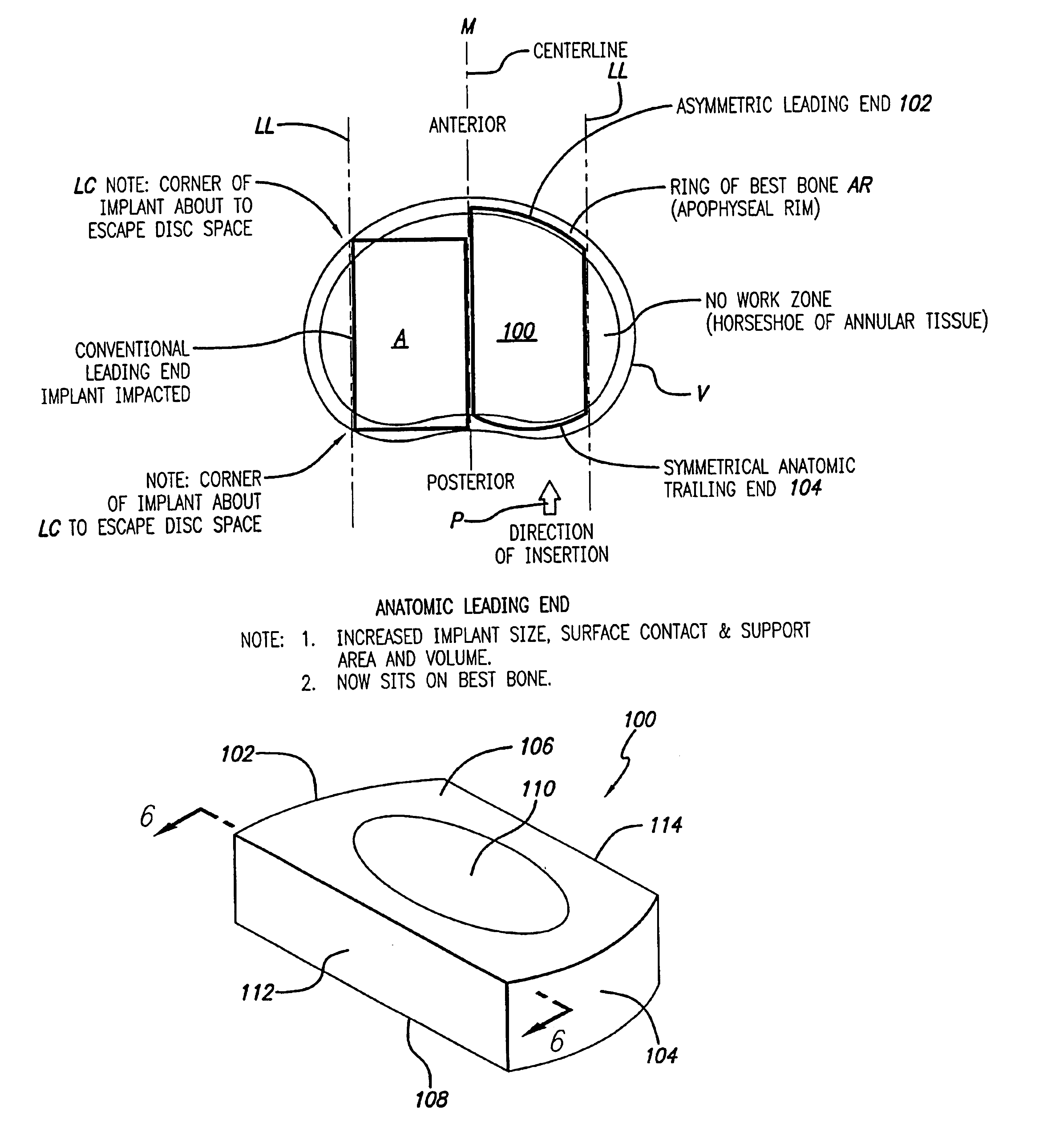
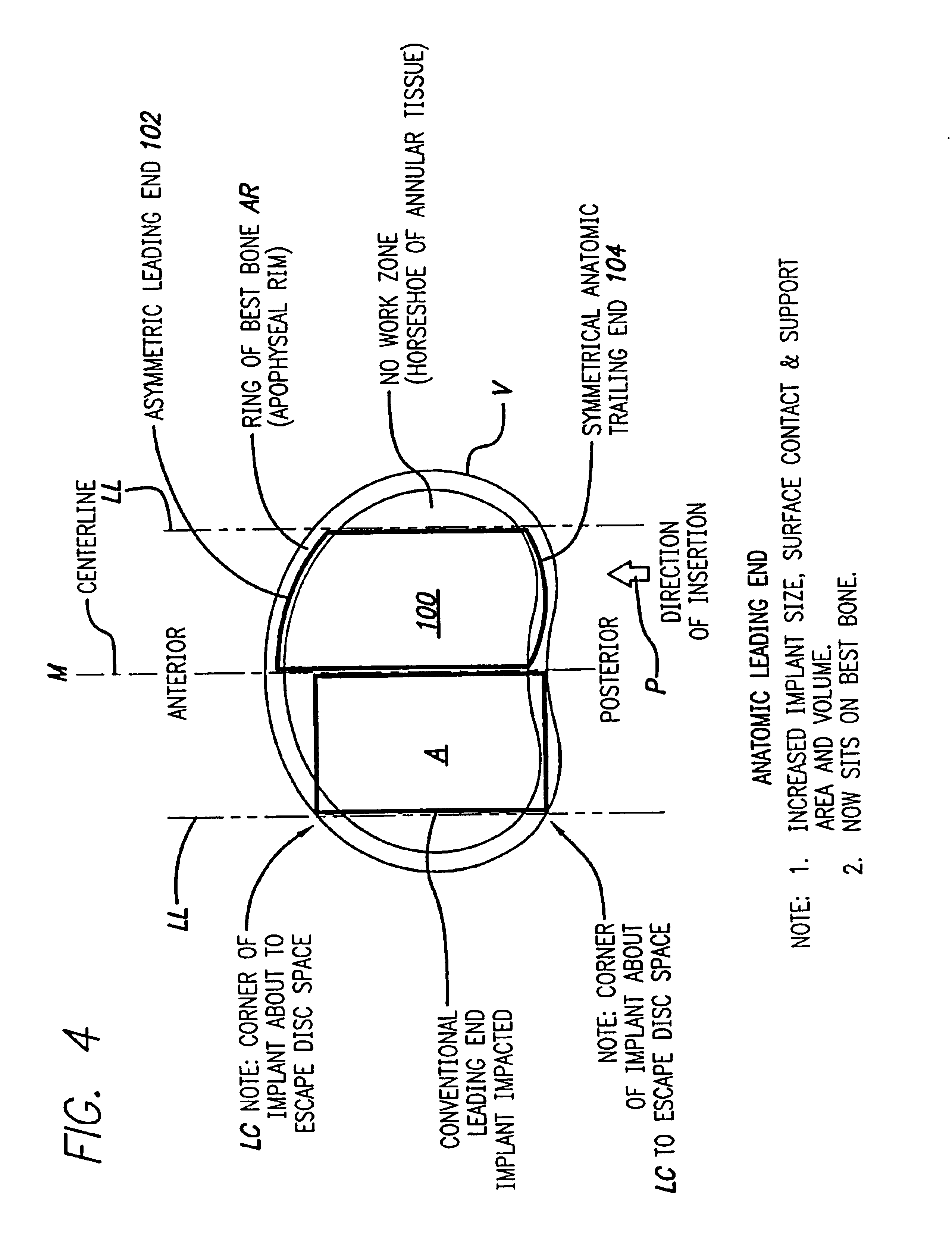
[0041]FIG. 4 shows an embodiment of the present invention comprising an interbody spinal implant generally referred by the numeral 100, inserted in the direction of arrow P from the posterior aspect of a vertebral body V on one side of the centerline M in the lumbar spine. In a preferred embodiment of the present invention, the implant can be made of bone that is either in a naturally occurring state, or can be made of a composite material comprising bone particles. In a naturally occurring state, the implant can be manufactured from a piece of bone obtained from a major long bone or other suitable source and can include bone dowels and diaphyseal bone rings, for example. Alternatively, the implants can be manufactured from a composite of bone made up of cortical fibers, bone filaments, bone particles, as examples. In addition to bone, the composite may also include a material which may or may not be bioactive and / or bioresorbable such as a plastic, ceramic, or other. Once formed, t...


PUM

PropertyMeasurementUnit
Lengthaaaaaaaaaa
Radiusaaaaaaaaaa

Abstract

An interbody spinal implant is formed of cortical bone adapted for placement across an intervertebral space formed across the height of a disc space between two adjacent vertebral bodies. An asymmetrical leading end on the implant is adapted to sit upon the peripheral areas, such as the apophyseal rim and the apophyseal rim area, of the vertebral end plate region of the vertebral bodies without protruding therefrom. The asymmetrical leading end allows for the safe use of an implant of maximum length for the implantation space into which it is installed. The implant can also include an asymmetric trailing end adapted to sit upon the more peripheral areas of the vertebral end plate region of the vertebral bodies.

Description

[0001]This application is a continuation of application Ser. No. 09 / 941,425, filed Aug. 28, 2001, now U.S. Pat. No. 6,666,890; which is a continuation of application Ser. No. 09 / 553,000, filed Apr. 19, 2000, now U.S. Pat. No. 6,350,283; the disclosures of which are incorporated herein by reference.BACKGROUND OF THE INVENTION[0002]1. Field of the Invention[0003]The present invention relates generally to interbody spinal implants preferably adapted for placement in pairs side by side to either side of the midline with or without a space therebetween into a space created across the height of a disc space and between two adjacent vertebral bodies, after the removal of damaged spinal disc material, for the purpose of correcting spinal disease at that interspace. The spinal implants comprise of cortical bone either in a form such as a material that may naturally be available from a body; or as a composite material of cortical bone in particles or spindles, and the like in a resorbable pla...

Claims


Application Information

Patent Timeline
IPC IPC(8): A61F2/44A61F2/00A61F2/02A61F2/28A61F2/30C10G1/00C10G1/08C10G47/00C10G47/04C10G47/12C10G65/10
CPCA61F2/4455A61F2/446C10G1/002C10G1/083C10G47/00C10G47/04C10G47/12C10G65/10A61F2/28A61F2310/00359A61F2002/2817A61F2002/30062A61F2002/30777A61F2002/30785A61F2002/30904A61F2002/4475A61F2002/448A61F2210/0004A61F2310/00023A61F2310/00029A61F2310/00131A61F2310/00179A61F2/442A61F2002/30593
Inventor MICHELSON, GARY K.
Owner WARSAW ORTHOPEDIC INC
Why Eureka
Try Eureka