
Coin processing machine having coin-impact surfaces made from laminated metal

a laminated metal and processing machine technology, applied in the direction of coin inlet, coin counter, coin inlet, etc., can solve the problems of achieving the decibel level at which normal conversational speech becomes difficult, and the noise level produced by the handling of coins, so as to reduce the noise level of coins and absorb more energy

Inactive Publication Date: 2002-09-19
CUMMINS-ALLISON CORP
View PDF0 Cites 49 Cited by
  • Summary
  • Abstract
  • Description
  • Claims
  • Application Information

AI Technical Summary

Benefits of technology

[0005] A coin processing machine of the present invention includes a coin input region for receiving the coins and a coin processing region for processing the coins received by the coin input region. The coin processing region performs at least one coin processing function, such as sorting the coins into denominations, counting the coins, valuing the coins, discriminating the coins, and arranging the coins in a particular order. The coin processing machine further includes a coin output region for receiving the coins that have been processed from the coin processing region. Typically, the coin path leads from the coin input region through the coin processing region and into the coin output region. The coin path is partially defined by a coin-impact surface made of a laminated metal, preferably laminated steel. The laminated metal acts to absorb more of the energy for the impact of the coins and, thus, reduces the noise levels produced by the coins.

Problems solved by technology

One of the problems with these machines is the noise level produced by the handling of coins.
When the machines are placed in an area populated with users or customers, the noise created by the impacting of coins on the metallic surfaces can attain a decibel level at which normal conversational speech becomes difficult.

Method used


Image

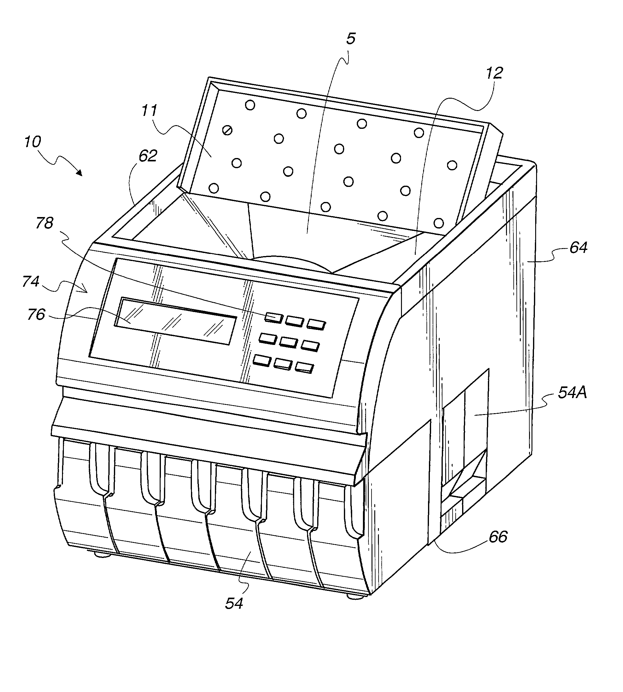
  • Coin processing machine having coin-impact surfaces made from laminated metal
  • Coin processing machine having coin-impact surfaces made from laminated metal
  • Coin processing machine having coin-impact surfaces made from laminated metal

Examples


Embodiment Construction

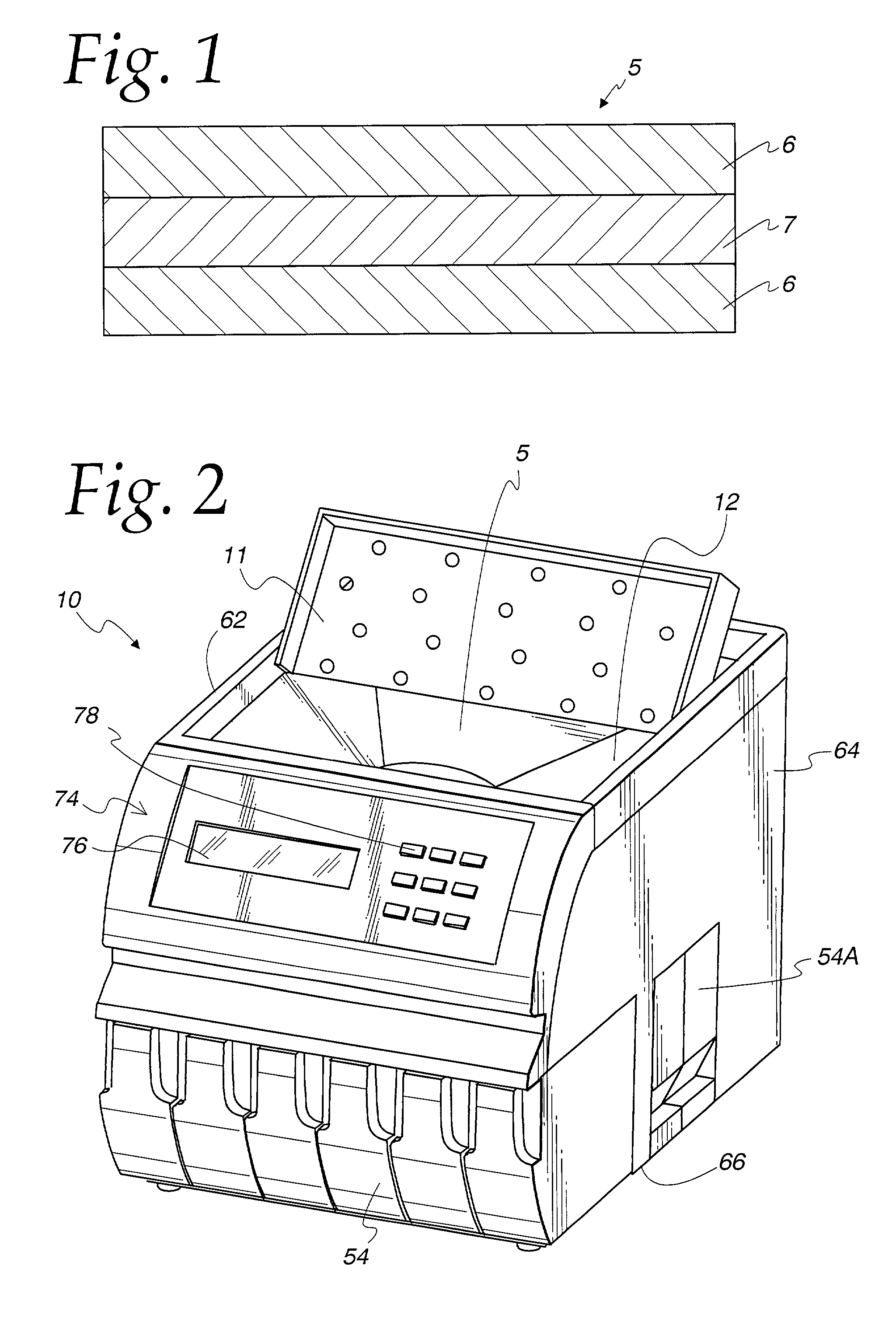
[0023] FIG. 1 illustrates a laminated material 5 having multiple layers. The outer two layers 6 are made of a metal, while the inner layer 7 is made of a non-metal that holds the outer two layers 6 together. The thin inner layer 7 of material 5 serves to dampen the vibrations of coins impacting the outer layers. The inner layer 7 converts the vibrational energy into thermal energy. The laminated material 5 comes in a variety of thicknesses, with the smallest one being about 0.04 inch and the largest being about 0.375 inch. Preferably, the laminated material 5 is a stainless steel. Such materials are available through various sources, including Classic Sheet Metal in Schiller Park, Ill.

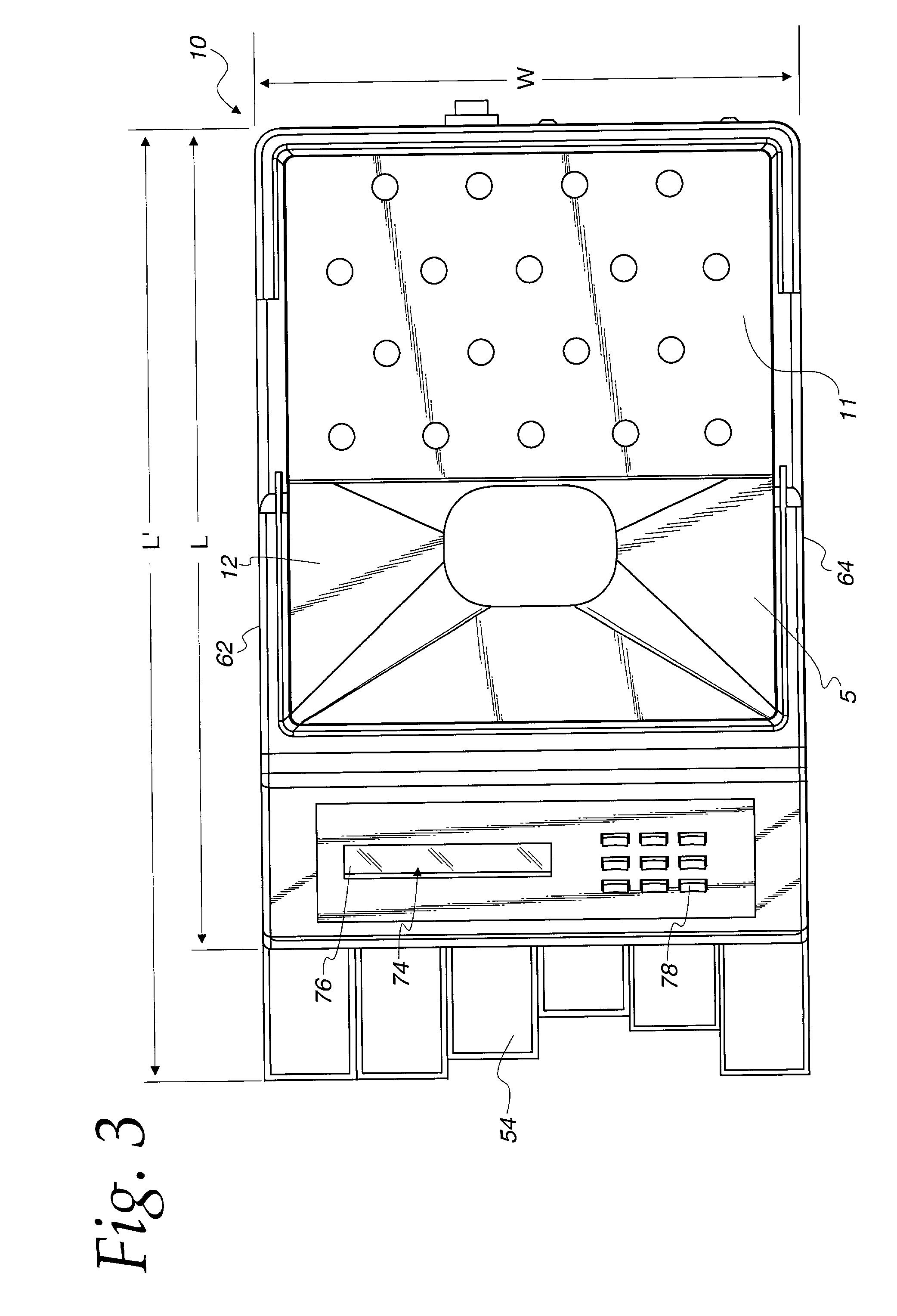
[0024] Turning now to the drawings of a coin processing machine, FIGS. 2-5 illustrate a coin sorter system 10 having several of its structures modified to include noise-deadening material, such as laminated material 5. In the coin entry region, the coin sorter system 10 includes a coin tray 12 which re...


PUM


Abstract

A coin processing machine of the present invention includes a coin input region for receiving said coins, a coin processing region for processing the coins, and a coin output region for receiving the coins that have been processed from the coin processing region. The processing machine includes a coin path leading from the coin input region, through the coin processing region, and into the coin output region. The coin path is partially defined by a coin-impact surface made of a laminated metal, preferably laminated steel. The laminated metal acts to absorb more of the energy for the impact of the coins and, thus, reduces the noise levels produced by coins.

Description

FIELD OF THE INVENTION[0001] The present invention relates generally to coin processing devices and, more particularly, to a type of coin processing device that reduces the noise levels by employing laminated metal on coin-impacting surfaces.BACKGROUND OF THE INVENTION[0002] Coin processing machines have been used for a number of years. There are several different types of processing machines. Coin sorters are used to sort coins of mixed denominations, usually so that each of the denominations can be counted. Coin wrappers receive coins of a particular denomination and arrange those coins in a stack so that a wrapping material, such as paper or plastic, can be placed around the coin stack. Coin redemption machines receive coins from a user and return to the user another item of value, such as paper currency, vouchers, or coupons. These coin processing machines may be large systems that are placed on the floor in banks, casinos, or retail stores. Alternatively, these machines may be ...

Claims


Application Information

Patent Timeline
IPC IPC(8): G07D3/06G07D3/12G07D9/00G07F1/04
CPCG07D3/06G07D3/128G07D9/00G07F1/048
Inventor CASANOVA, SCOTT D.KUHLIN, STEVEN S.QUINN, RICHARD J.
Owner CUMMINS-ALLISON CORP
Learn More