
Dome switch

a dome switch and switch body technology, applied in the field of dome switches, can solve the problems of difficult miniaturization of single switches, difficulty in getting thin thicknesses of single switches, and inability to get watertight structures

Inactive Publication Date: 2002-09-19
YAZAKI CORP
View PDF0 Cites 25 Cited by
  • Summary
  • Abstract
  • Description
  • Claims
  • Application Information

AI Technical Summary

Benefits of technology

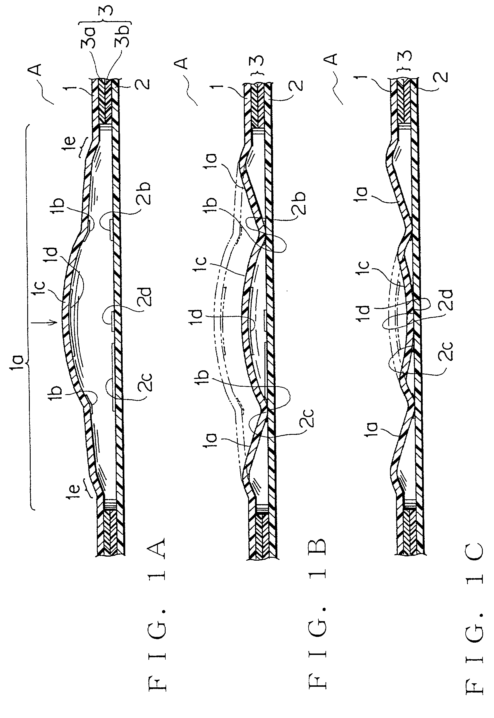
[0022] In the above-mentioned structure, the dome switch can be thinner and more compact and water-tighten easily. Furthermore, any locking piece provided on a back side of the electric circuit body is not required, then the dome switch can be mounted easily on a surface of an equipment.
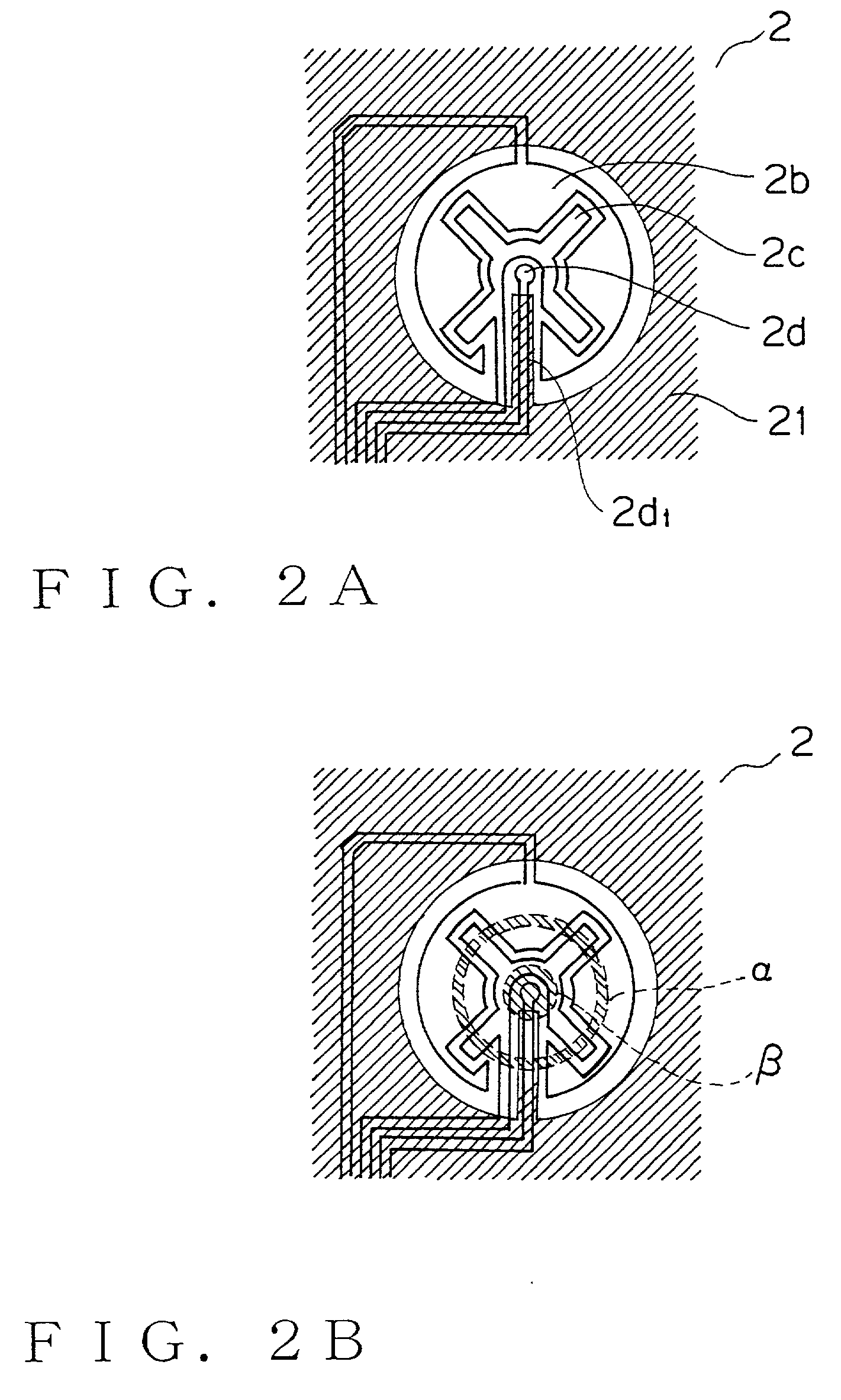
[0058] A dome switch according to this invention is structured by a single switch comprising a front sheet having a domed projection which projects outside and can turn over to the back side and is provided at the back side thereof with an electrode; an electric circuit body having an electric contact contacting with the electrode provided at the back side of the projection when the domed projection is turned over; and a domed convex portion provided near the center of the domed projection. In process of pushing the convex portion, firstly the projection turns over and an electrode provided near the periphery of the convex portion at the back side of the front sheet contacts with the electric contact provided on the electric circuit body and secondly an electrode provided near the center of the domed convex portion at the back side of the front sheet contacts with the electric contact provided on the electric circuit body. Therefore, the dome switch has a simple and reliable structure and is easily miniaturized, water-tightened and thinned, can be operated securely with click feeling.

Problems solved by technology

In such two-step switch, a rubber contact locking piece projects from a rear surface of an electric circuit body to be an obstacle to mount the electric circuit body on a surface in an equipment with a double-side adhesive tape or the like.
Therefore, getting watertight structure is hindered and also getting thinner thickness of a single switch portion becomes difficult.
Two respective single switches are required to have three conditions which are OFF+OFF, ON+OFF and ON+ON so that miniaturization of the single switch is difficult.

Method used


Image

  • Dome switch
  • Dome switch
  • Dome switch

Examples


Embodiment Construction

[0083] A rocker-type combined switch of an embodiment according to this invention will be described with reference to the attached drawings. FIG. 1A, 1B and 1C are sectional conceptual drawings, showing action of a single switch A.

[0084] In FIG. 1A, mark 1 is a front sheet (made of polyethylene terephthalate, PET, in this embodiment) having a domed projection 1a, projecting outside, capable of turning over to a back side and provided at the back side with an electrode. The single switch A is provided with an electric circuit body 2 (made of a flexible printed circuit, FPC, in this embodiment, but not limited FPC in this invention) having electrical contacts 2b, 2c to contact with an electrode 1b provided at the back side of the domed projection 1a when the domed projection 1a (diameter is 14 mm) is turned over. The domed projection 1a is provided concentrically in the center thereof with other domed convex portion 1c (diameter is 7 mm).

[0085] An electric contact pattern of the elect...


PUM


Abstract

A compact, thinned and water-tightened combined switch, is structured by a single switch comprising a front sheet having a domed projection which can be reversed to the back side and is provided at the back side with an electrode, an electric circuit body having an electric contact to contact with the electrode and a domed convex portion provided in the vicinity of the center of the domed projection. In operation process, firstly the projection is reversed and an electrode provided near the periphery of the convex portion contacts with the electric contact on the electric circuit body and secondly an electrode provided in the vicinity of the center of the domed convex portion contacts with the electric contact on the electric circuit body.

Description

BACKGROUND OF THE INVENTION[0001] 1. Field of the Invention[0002] This invention relates to a dome switch having multiple switching function.[0003] 2. Description of the Related Art[0004] A two-step switch is used frequently for a window regulator switch in a car. The first step switch operation, pushed by a finger with click feeling, makes a window glass moved and if the finger is left from the switch on the condition, the window glass is stopped. However, when pushing the switch more over the first step switch operation, the window glass moves continuously until reaching to a specified position (top end or bottom end) even if the finger is left from the switch.[0005] Such two-step switch is usually constituted with combining at least two single switches. An example of a rocker-type combined switch, applied by the two-step switch (example of two rocker-type combined switches mounted on) is shown in FIG. 12, 13A, 13B and 13C.[0006] FIG. 12 is an exploded perspective view of the swit...

Claims


Application Information

Patent Timeline
IPC IPC(8): H01H11/00H01H13/64H01H13/48H01H13/702H01H23/00H01H23/30
CPCH01H13/44H01H13/702H01H23/003H01H2203/044H01H2205/002H01H2205/016H01H2215/006H01H2215/016H01H2225/006H01H2225/018H01H2213/01
Inventor KAWAGUCHI, KENICHIROKUBOTA, MINORUMORI, SEIJI
Owner YAZAKI CORP
Learn More