Multiple-interface selection system for computer peripherals

a selection system and peripheral technology, applied in the direction of electromagnetic radiation sensing, coupling device connection, instruments, etc., can solve the problem of not being able to perform a typical user's desired field operation

Inactive Publication Date: 2002-09-19
PSC SCANNING INC
View PDF0 Cites 15 Cited by
  • Summary
  • Abstract
  • Description
  • Claims
  • Application Information

AI Technical Summary

Benefits of technology

0007] The present invention relates to an interface selection system for a computer peripheral in which configuration for the peripheral and/or its host is at least in part accomplished through the interface connector cable. In a preferred embodiment, the computer peripheral is equipped with one or more hardware interfaces. The interface connector cable has a first end connector for attaching to the computer peripheral. The first end connector of the interf

Problems solved by technology

Such an operation typically requires the expertise of an electronics technician or sk

Method used


Image

  • Multiple-interface selection system for computer peripherals
  • Multiple-interface selection system for computer peripherals
  • Multiple-interface selection system for computer peripherals

Examples


Embodiment Construction

[0024] The preferred embodiments will now be described with reference to the drawings.

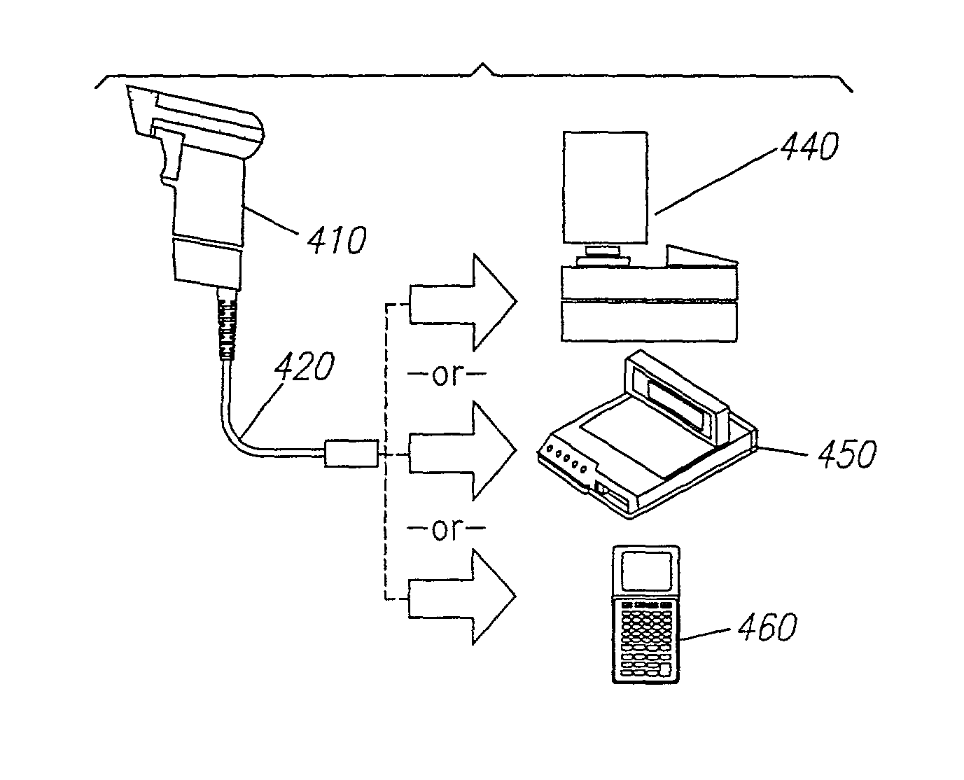
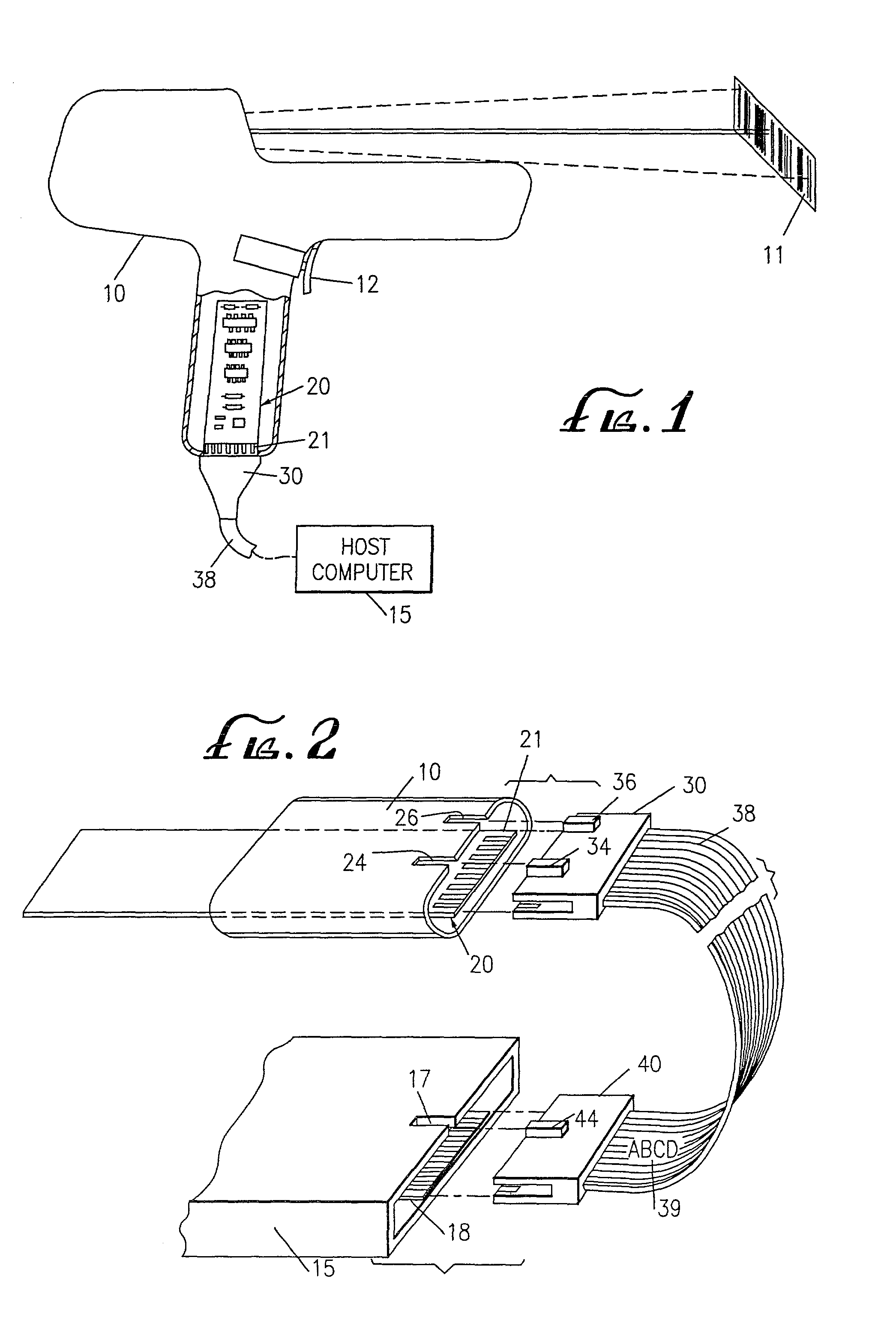
[0025] In FIG. 1, an example computer peripheral is illustrated as a handheld laser scanner 10 used for scanning a bar code 11. The scanner 10 is operably connected to a host interface (diagrammatically illustrated as a computer 15) via an interconnect cable 38. The interconnect cable 38 includes an end plug or edge connector 30 which connects to a mating connector 21 on the end of a printed circuit board 20 within the scanner 10. The interconnect cable 38 provides a communication link between the host computer 15 and the laser scanner 10 and may also provide power to the scanner 10.

[0026] Referring to FIG. 2, the interconnect cable 38 has a first end connector 30 which plugs into the scanner 10 attaching to the edge connector 21 of the circuit board 20, and a second end connector 40 which plugs into the host computer 15 attaching to the edge connector 18. The first end connector 30 includes tabs 3...


PUM


Abstract

An interface selection and configuration system for a computer peripheral in which configuration for the peripheral and/or the host interface is at least in part accomplished by the interface connector cable. In a preferred embodiment, the computer peripheral is equipped with one or more hardware interfaces. The interface connector cable has a first end connector for attaching to the computer peripheral. The first end connector of the interface connector cable is typically a multiple pin connector constructed and arranged to be properly physically and electrically connectable only to a specific computer peripheral or class of computer peripherals, the first end connector including at least one electrical connection between two pins for completing a circuit within the computer peripheral thereby enabling the computer peripheral. Where the peripheral is a data reading device such as a laser scanner or RFID reader, alternate or additional configuration may be obtained, with data reading device, from the label on the interconnect cable. The label, which may for example be a bar code or RFID tag, contains information or instructions by which the data reading device (and/or the host) is configured.

Description

RELATED APPLICATIONS[0001] This application is a continuation of Ser. No. 09 / 268,263 filed Mar. 15, 1999 U.S. Pat. No. 6,293,467, which is a divisional of Ser. No. 08 / 955,864 filed Oct. 21, 1997 U.S. Pat. No. 5,905,249, which is a continuation of Ser. No. 08 / 706,736 filed Sep. 9, 1996 U.S. Pat. No. 5,703,347, which is a continuation of Ser. No. 08 / 305,517 filed Sep. 13, 1994 U.S. Pat. No. 5,563,402, which is a continuation-in-part of application Ser. No. 08 / 039,606 filed Mar. 25, 1993 U.S. Pat. No. 5,347,113, which is a continuation-in-part of Ser. No. 08 / 034,189 filed Mar. 22, 1993 U.S. Pat. No. 5,330,370, which is a continuation of application Ser. No. 07 / 788,267 filed Nov. 4, 1991, abandoned.BACKGROUND OF THE INVENTION[0002] The field of the present invention relates to interconnection systems for computers and computer peripherals or more specifically, methods and devices for selecting proper interface between a computer peripheral and its host interface such as may include a co...

Claims


Application Information

Patent Timeline
IPC IPC(8): G06F1/18G06F3/00G06K7/10H01R13/46H01R13/64H01R29/00H01R31/06
CPCG06F1/18G06F3/002G06K7/10G06K7/10881G06K2207/1017H01R13/465H01R13/64H01R29/00H01R31/06H01R12/7076
Inventor REDDERSEN, BRAD R.SHEPARD, PHILLIP W.MOCH, ROCKIE D.WILLIAMS, JON PAUL CHARLES
Owner PSC SCANNING INC
Why Eureka
Try Eureka