Eureka AIR delivers breakthrough ideas for toughest innovation challenges, trusted by R&D personnel around the world.

System and method for detecting slave power supply failure

Inactive Publication Date: 2002-09-19
TAIWAN SEMICON MFG CO LTD
View PDF0 Cites 4 Cited by
  • Summary
  • Abstract
  • Description
  • Claims
  • Application Information

AI Technical Summary

Problems solved by technology

Predictability, reliability, repeatability and cost are critical in an application such as this, where a malfunction in a power supply may result in the stoppage of a production line.
The production loss and the subsequent rework may cost millions of dollars in lost profits.
However, the slave power supply 120 might not be able to deliver the desired power output as specified by the set point 150.
This could be due to lack of capacity, for example, or due to some other malfunction.
Furthermore, this need is harder to address by a user of a power supply system 130 than it would be by the power supply developer.
That is, when an existing power supply system must be retrofitted for detection of the slave power supply malfunction and triggering of an interlock there are more constraints than there would be if detection and interlocking were being designed for a power supply system during development of the system.
A "malfunction" of the system occurs when the system fails to operate normally.
If the control circuitry is not able to regulate the power supply output voltage, for example, this is abnormal and is thus a malfunction of the power supply.

Method used


Image

  • System and method for detecting slave power supply failure
  • System and method for detecting slave power supply failure
  • System and method for detecting slave power supply failure

Examples


Embodiment Construction

[0026] While the invention is susceptible to various modifications and alternative forms, specific embodiments thereof are shown by way of example in the drawings and will be described herein in detail. It should be understood, however, that the drawings and detailed description thereto are not intended to limit the invention to the particular form disclosed, but on the contrary, the intention is to cover all modifications, equivalents and alternatives falling within the spirit and scope of the present invention as defined by the appended claims.

[0027] Elements which appear in more than one FIG. herein are numbered alike in the various FIGS.

[0028] FIGS. 4a, 4b, 4c and 4d illustrate aspects of discoveries resulting from analysis of and experimentation with an existing power supply system 130.

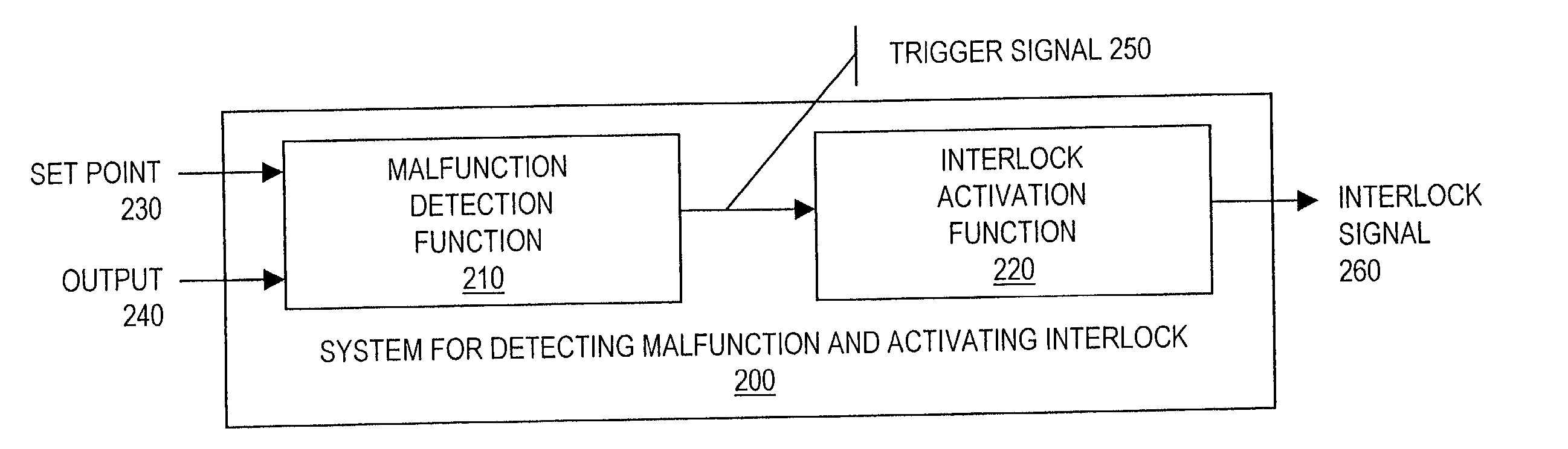
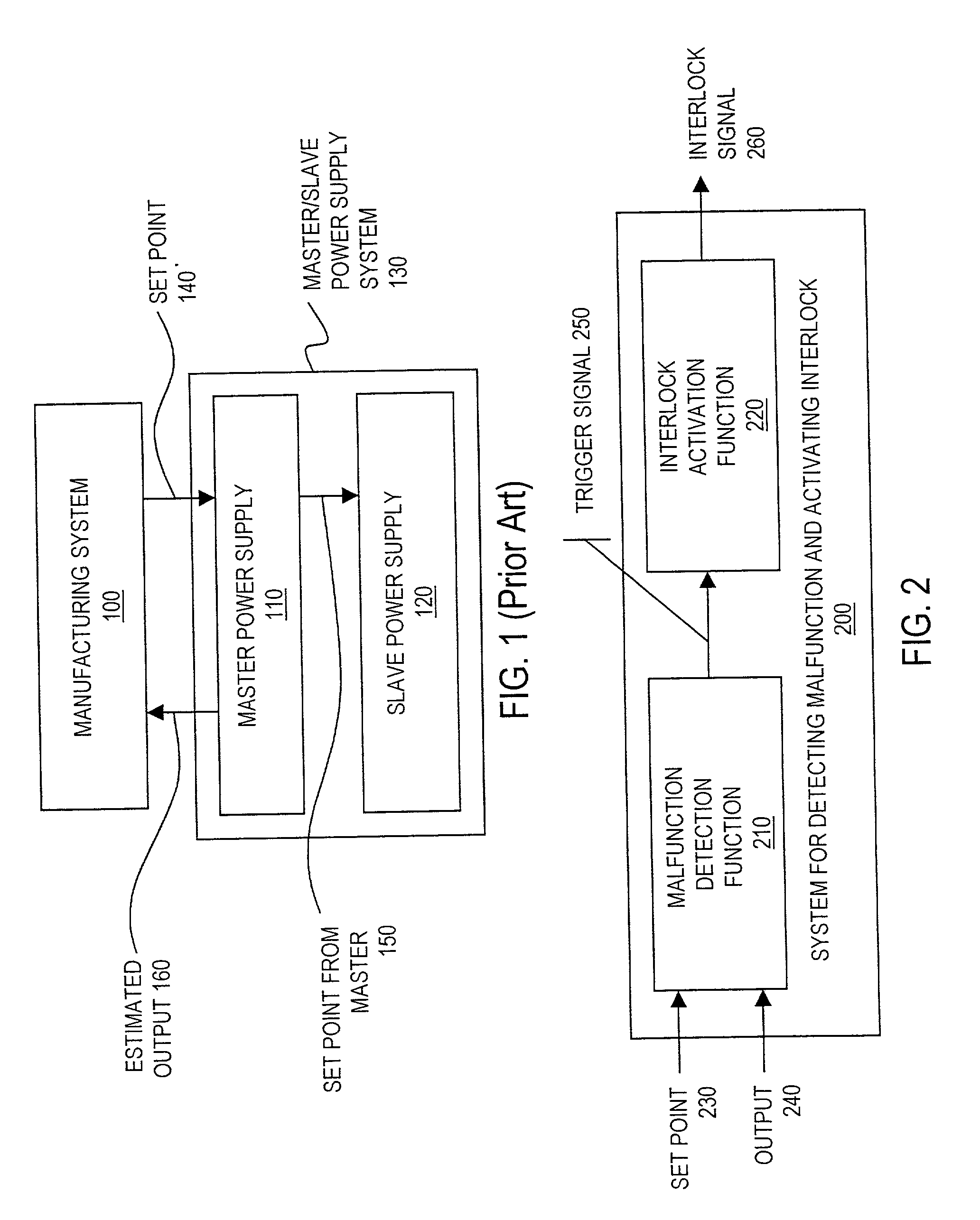
[0029] For the present invention there was a need to retrofit an existing power supply system 130 for detecting a malfunction of the slave power supply, and for triggering of an interlock. As sta...


PUM


Abstract

A system and method for detecting a malfunction of a slave power supply and triggering an interlock signal in response to the detection of the malfunction. The method for activating an interlock signal on detecting a malfunction of a slave power supply, includes receiving first and second inputs. In one embodiment, the first input received represents status of a set point, and the second input represents output power. On receiving the inputs the method determines that the slave power supply system has malfunctioned when the received inputs substantially mismatch. In response to the determination of the malfunction, an interlock signal is activated. The system to implement the method includes a first circuit section and a second circuit section. The first circuit section is configurable to receive a first signal representing status of the set point for the output power and a second signal representing the output power of the power supply system. The first circuit section is configurable to activate a trigger signal when the first and second signals substantially mismatch. The second circuit section, which is electrically coupled to the first circuit section, is configurable to activate the interlock signal in response to receiving the trigger signal. In one embodiment, the system to implement the method includes a processing unit, memory coupled to the processing unit and a program included in the memory, where the program is executable to implement the method.

Description

[0001] 1. Field of the Invention[0002] The present invention relates to the field of power supplies, and more particularly to detecting a malfunction of a slave power supply and triggering an interlock signal in response to the detection of the malfunction.[0003] 2. Description of the Relevant Art[0004] As defined herein, a "power supply" is a device for the conversion of available power of one set of characteristics to another set of characteristics to meet specified requirements. In a typical application of a power supply, raw input power available in the form of 110V AC or 220V AC is converted to a controlled or stabilized voltage. A power supply system may include a number of power supplies coupled together. Examples of electrical parameters, properties or characteristics which are typically specified for a power supply may include output power, output voltage, output current, input voltage, input current, percent regulation, ripple effect, load impedance, resolution, and accura...

Claims


Application Information

Patent Timeline
IPC IPC(8): G01R31/317G06F1/28G06F19/00
CPCG01R31/31721
Inventor CHAO, CHANG-HUICHIANG, WEN-HUANGCHANG, HUNG-YI
Owner TAIWAN SEMICON MFG CO LTD
Why Eureka
Eureka Blog
Learn More