
Laser parking alignment system

a technology of parking alignment and laser, which is applied in the field of laser system, can solve the problems of difficult to correctly align vehicles within confined areas, inability to close the garage door, and inconvenient access to the front of the vehicle,

Inactive Publication Date: 2002-10-03
SIMON CHRISTOPHER M
View PDF0 Cites 20 Cited by
  • Summary
  • Abstract
  • Description
  • Claims
  • Application Information

AI Technical Summary

Problems solved by technology

It is well known that it can be very difficult to correctly align vehicles within confined areas, such as garages.
If the vehicle is not positioned far enough within the garage, the garage door is unable to be closed.
In addition, if the vehicle is parked too far within the garage, the area may be too confined to allow people to traverse in front of the vehicle.
Also, in an attempt to position the vehicle far enough within the garage to allow the garage door to close, the driver may accidently hit objects, such as the garage wall.
However, the ball alignment device does not allow for modification of the size of the vehicle.
However, utilizing these bumpers actually provides a late notice to the drive, since the vehicle has actually contacted the bumpers, which may cause damage to the vehicle.
Although Barkley discloses a light beam for aligning a vehicle, Barkley does not teach or suggest emitting the light beam directly on the vehicle to provide an indication that the vehicle is properly aligned.
Barkley suffers from the disadvantage of utilizing several electronic components, thereby providing an expensive and complex system.
In addition, Viskovich suffers from a serious defect, in which the driver is devoting a great deal of attention to the rear of the vehicle, which could be danger to people or objects located in front of the vehicle.
Although White discloses a laser emitting device to assist in the alignment of a vehicle within a confined area, White does not teach or suggest positioning the laser emitting device overhead the vehicle.
First, the emitted laser is directed toward the eyes of the driver of a vehicle, which can be very distracting, resulting in a safety hazard.
The target alignment device may not be desired by many vehicle owners, since it may detract from the aesthetic beauty of the vehicle's interior.
Lewis also does not teach or suggest mounting the laser overhead within the enclosure.
Additional, Lewis's system may only be used by vehicles having the mounting bracket and laser.

Method used


Image

  • Laser parking alignment system
  • Laser parking alignment system
  • Laser parking alignment system

Examples


Embodiment Construction

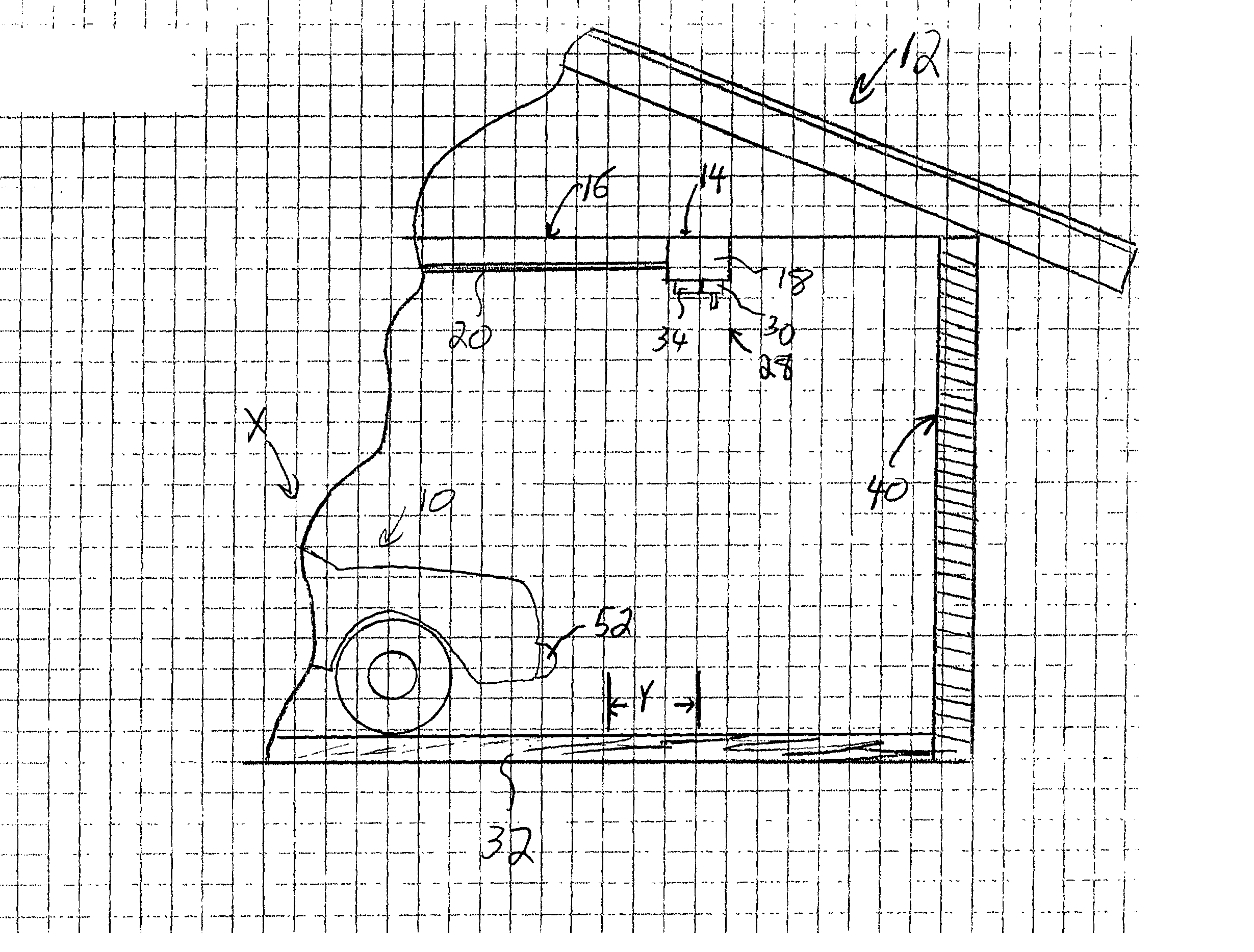
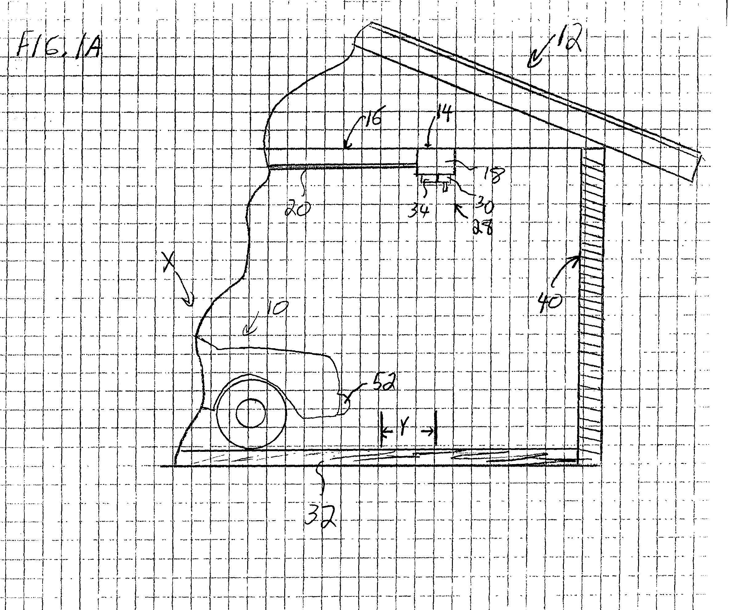
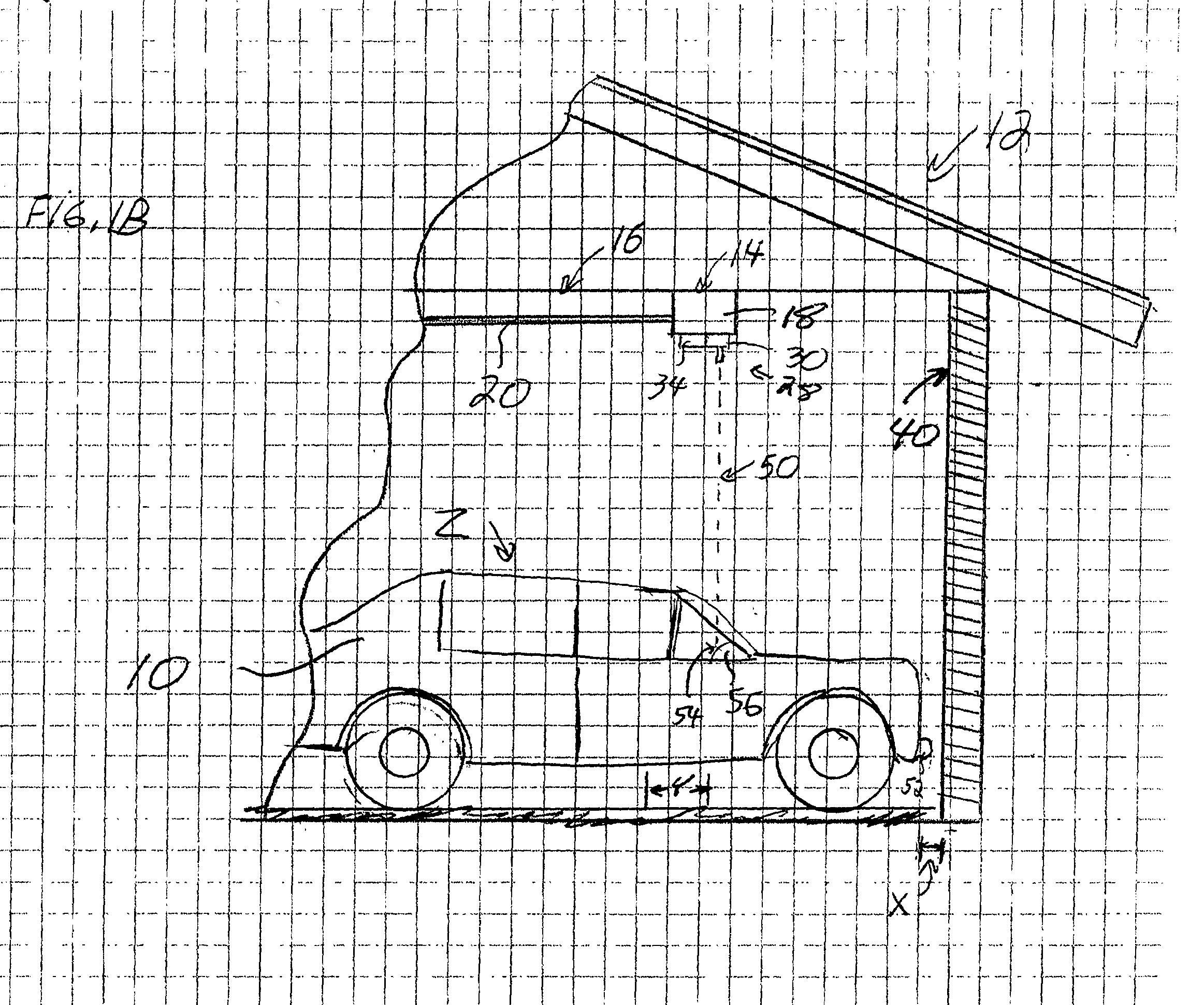
[0022] A laser system for properly positioning a vehicle in a specified area is disclosed. FIG. 1A is a partial side sectional view of a vehicle 10 in a partially parked position X within a garage 12. The vehicle may be any vehicle such as an automobile, truck, bus, etc. Although a garage is illustrated, any enclosure having a plurality of walls and a ceiling may be used. A conventional garage door opener 14 is affixed to a ceiling 16 of the garage. The garage door opener includes a motor 18 driving a chain 20 connected to a garage door (not shown).

[0023] A laser alignment system 28 includes a laser emitter 30, which is affixed to a bottom portion of the garage door opener 14. The laser emitter emits a laser beam downwardly toward the ground 32. The laser emitter may be any device which emits a light (e.g., laser or infrared light beam) or even an electromagnetic pulse. In the preferred embodiment of the present invention, the laser emitter is a convention 3-volt laser. Adjacent the...


PUM


Abstract

A parking alignment system utilizing a laser to properly align a vehicle within a garage. The alignment system includes a laser emitter which emits a downwardly pointing laser beam. A driver of the vehicle enters the enclosure and stops the vehicle in a specified position providing proper alignment of the vehicle within the garage when the laser beam strikes a specified target indication position located on the vehicle. The parking alignment system may be actuated by a motion detector detecting motion within the garage.

Description

[0001] 1. Technical Field of the Invention[0002] This invention relates to alignment systems, and more particularly, to a laser system for aligning a vehicle in a specified area.[0003] 2. Description of Related Art[0004] It is well known that it can be very difficult to correctly align vehicles within confined areas, such as garages. Many times a driver must estimate the position of the vehicle when aligning it within the garage. If the vehicle is not positioned far enough within the garage, the garage door is unable to be closed. In addition, if the vehicle is parked too far within the garage, the area may be too confined to allow people to traverse in front of the vehicle. Also, in an attempt to position the vehicle far enough within the garage to allow the garage door to close, the driver may accidently hit objects, such as the garage wall. There have been implemented many ways to properly align the vehicle within the garage. Many drivers utilize a stationary object for which the...

Claims


Application Information

Patent Timeline
Patent Type & Authority Applications(United States)
IPC IPC(8): E04H6/42
CPCE04H6/426
Inventor SIMON, CHRISTOPHER M.
Owner SIMON CHRISTOPHER M
Learn More