Image reproducing device

a technology of image reproduction and image, which is applied in the field of video reproducing equipment, can solve the problems of package damage to the interior design decorated inside the limited vehicle compartment, increase in the thickness of the elaborately designed portion at the bottom of the ceiling of the vehicle, and deterioration of the operability of insertion and rejection of information memory media such as a disk

Active Publication Date: 2002-10-17
AUTO TECH GRP LLC
View PDF2 Cites 143 Cited by
  • Summary
  • Abstract
  • Description
  • Claims
  • Application Information

AI Technical Summary

Benefits of technology

0093] The best mode for carrying out this invention will now be described about the structure, operation and effect with reference to the accompanying drawings.

Problems solved by technology

Particularly, it involves increase in the thickness of the elaborately designed portion at the bottom of the ceiling of the vehicle, enlargement of the projected area of disposition or installation on the ceiling of the vehicle, and deterioration of the operability of insertion and rejection of the information memory medium such as a disk, or the like.
In addition, the package injures the interior design decorated inside the limited vehicle compartment.
Further, in case there is provided a port for inserting thereinto and ejecting therefrom, an information memory medium such as a disc, or the like, enough clearance cannot be secured in the ceiling of the vehicle, impairing the operability of insertion and ejection into / from the disc.
Still further, since there is provided a remote controller for operating the equipment separate from the body of the equipment itself, when a user tries to use the remote controller, it is often lost, leading to have the trouble of searching it inside the vehicle compartment.

Method used


Image

  • Image reproducing device
  • Image reproducing device
  • Image reproducing device

Examples


first embodiment

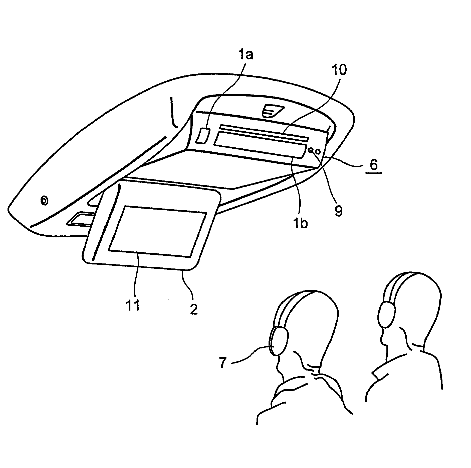
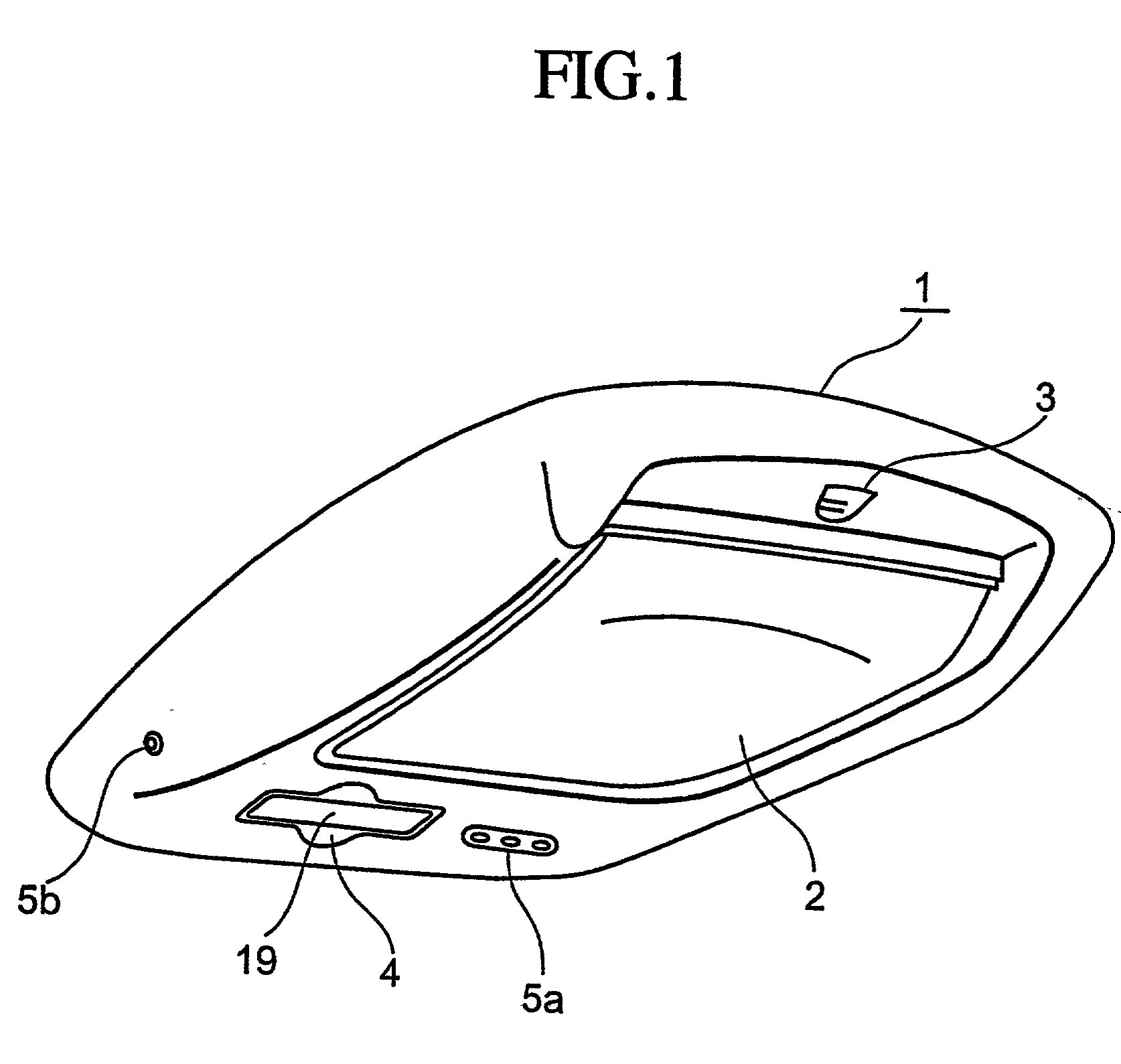
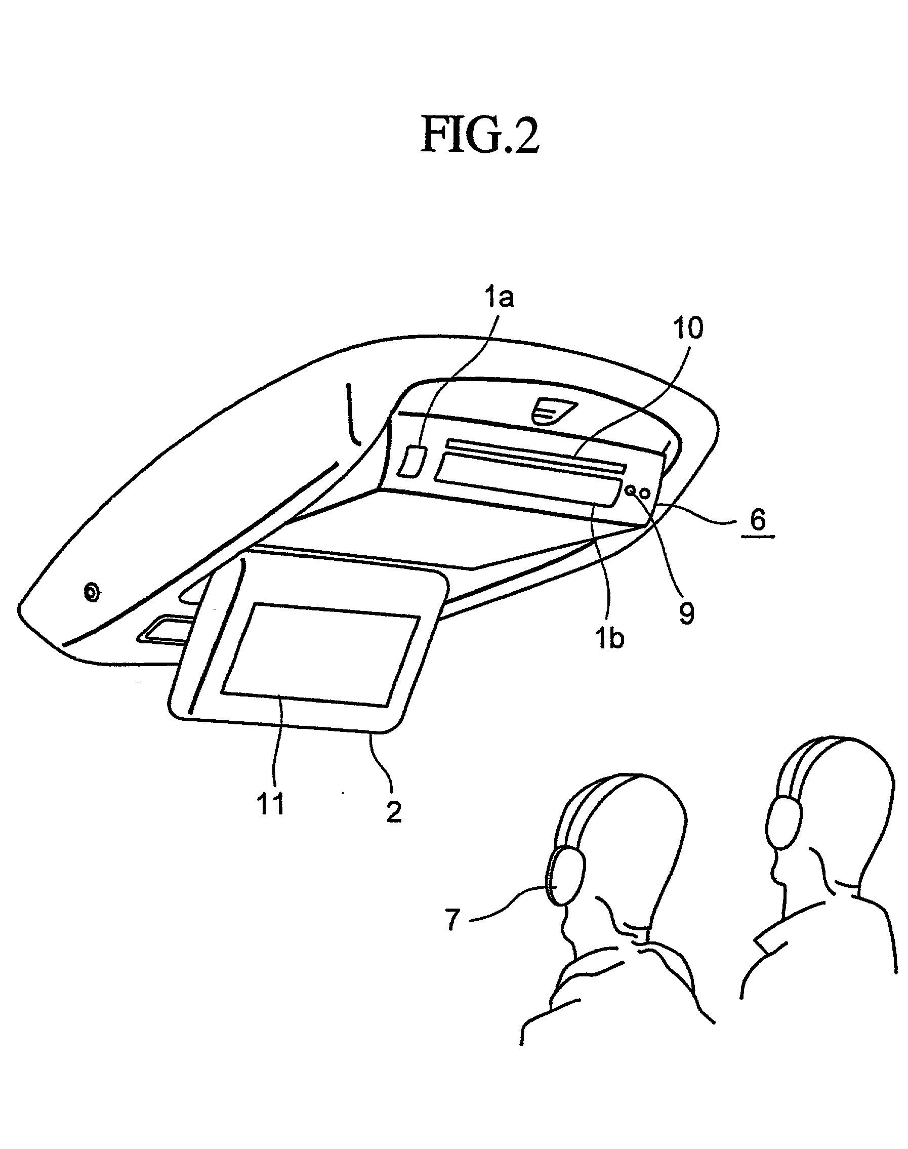
[0095] The video reproducing equipment in the first embodiment is disposed on a ceiling of a vehicle compartment. FIG. 1 shows a state in which the display monitor 2 is closed. When an open / close button 3 is pushed in this state, the display monitor 2 and the reproducing unit 6 for a DVD player, or the like, are opened as shown in FIG. 2 to bring a user seated on a rear seat in the vehicle into a state ready for looking videos and listening to sounds, respectively.

[0096] On a bottom surface of a body base cover 1, headphone output terminals 5a are provided. As means for listening to the sounds, aside from the method of listening to them by coupling connection terminals to the headphone output terminals 5a, there are several ways as shown in the followings. The first way is to listen to the sounds by converting the sound signals to, e.g., infrared or radio frequency signals (RF signals), or the like, to wirelessly transmit them to the wireless headphone(s) 7 worn by the user(s). On a...

second embodiment

[0134] Next, as the second embodiment, an example is given in which the display monitor 2 and the reproducing unit 6 are disposed in the front and rear (back and forth) position on a plane. FIGS. 23 through 30 show the structure of the video reproducing unit in the second embodiment.

[0135] FIG. 23 is a side view showing the entire structure of the video reproducing unit in the second embodiment. In this example, the shaft of the display monitor 2 and the shaft of the reproducing unit 6 are disposed close to each other. In a state in which the equipment is closed, the surface of the display screen 11 of the display monitor 2 faces outside of the body base cover 1.

[0136] FIG. 24 is a side view showing a state in which the display monitor 2 and the reproducing unit 6 of the video reproducing unit in the second embodiment are opened. As shown in FIG. 24, a structure has taken in which, when the equipment is opened, the display monitor 2 and the reproducing unit 6 are erected by reversel...

third embodiment

[0150] Next, as the third embodiment, an example is given in which plural pieces of subunits 69 having a slot opening 70 are disposed as a constituent in the reproducing unit 6 of the first embodiment. FIGS. 31 through 37 show the structure of the video reproducing unit in the third embodiment.

[0151] FIG. 31 is a perspective view showing an example of the reproducing unit 6 of the video reproducing unit in the third embodiment. In FIG. 31, as an object that can be inserted into / rejected from the slot opening 70, there may be a media such as a magnetic disc, an optical disc, a card-type memory or a stick-type memory to be used in Personal Computer Memory Card International Association (PCMCIA), or the like, as well as an arbitrary constituent such as an expansion circuit board or a subunit 69 body.

[0152] FIGS. 32 through 37 show a mounting and dismounting structure of the remote controller 19 in the third embodiment. Here, as an example of the subunit 69 in FIG. 31, there is shown an...


PUM


Abstract

In an integrated type video reproducing equipment having a reproducing unit for reproducing the video information, a display unit for displaying the reproduced video information, and a chassis for supporting them, the equipment is provided with supporting means for supporting the displacement of both the units,,and fixing means for fixing the displacement so that both the units are able to displace in a predetermined direction and to fixe and house in a predetermined position. Thus, there is provided a small-sized video reproducing equipment which is superior in the operability and visibility when in use as well as in the housing efficiency when housed.

Description

[0001] This invention relates to a field of video reproducing equipment which reproduces and displays video information, and in particular to a video reproducing equipment which is disposed or installed on a ceiling, or the like, inside a compartment of a vehicle. Specifically, for example, this invention relates to a video reproducing equipment for video / image recording and reproducing by utilizing a digital versatile disk (DVD) player and a liquid crystal color display, or television, video, Internet communication, or the like.[0002] Conventionally, a video reproducing equipment able to house a display in a ceiling of a vehicle compartment has been known. This kind of video reproducing equipment is described in numerous documents. For example, Published Japanese Utility Model Registration Application No. 15479 / 1989, Published Japanese Utility Model Registration Application No. 137048 / 1986, and Published Japanese Patent Application No. 149083 / 1990 disclosed that looking and listeni...

Claims


Application Information

Patent Timeline
Patent Type & Authority Applications(United States)
IPC IPC(8): B60R11/00B60R11/02
CPCB60R11/0211B60R11/0235B60R2011/0085B60R2011/0082B60R2011/0028
Inventor NAGATA, SHIGERUKURODA, TOSHIYUKIKOMATSU, YASUOKITANO, TOYOAKISAGA, IKUO
Owner AUTO TECH GRP LLC
Why Eureka
Try Eureka