Rail welderhead shear apparatus

Inactive Publication Date: 2002-10-24
HOLLAND CO
View PDF4 Cites 91 Cited by
  • Summary
  • Abstract
  • Description
  • Claims
  • Application Information

AI Technical Summary

Problems solved by technology

Of recent significance has been the addition of the rail stretching or pulling procedure, which has heretofore been u...

Method used


Image

  • Rail welderhead shear apparatus
  • Rail welderhead shear apparatus
  • Rail welderhead shear apparatus

Examples


Embodiment Construction

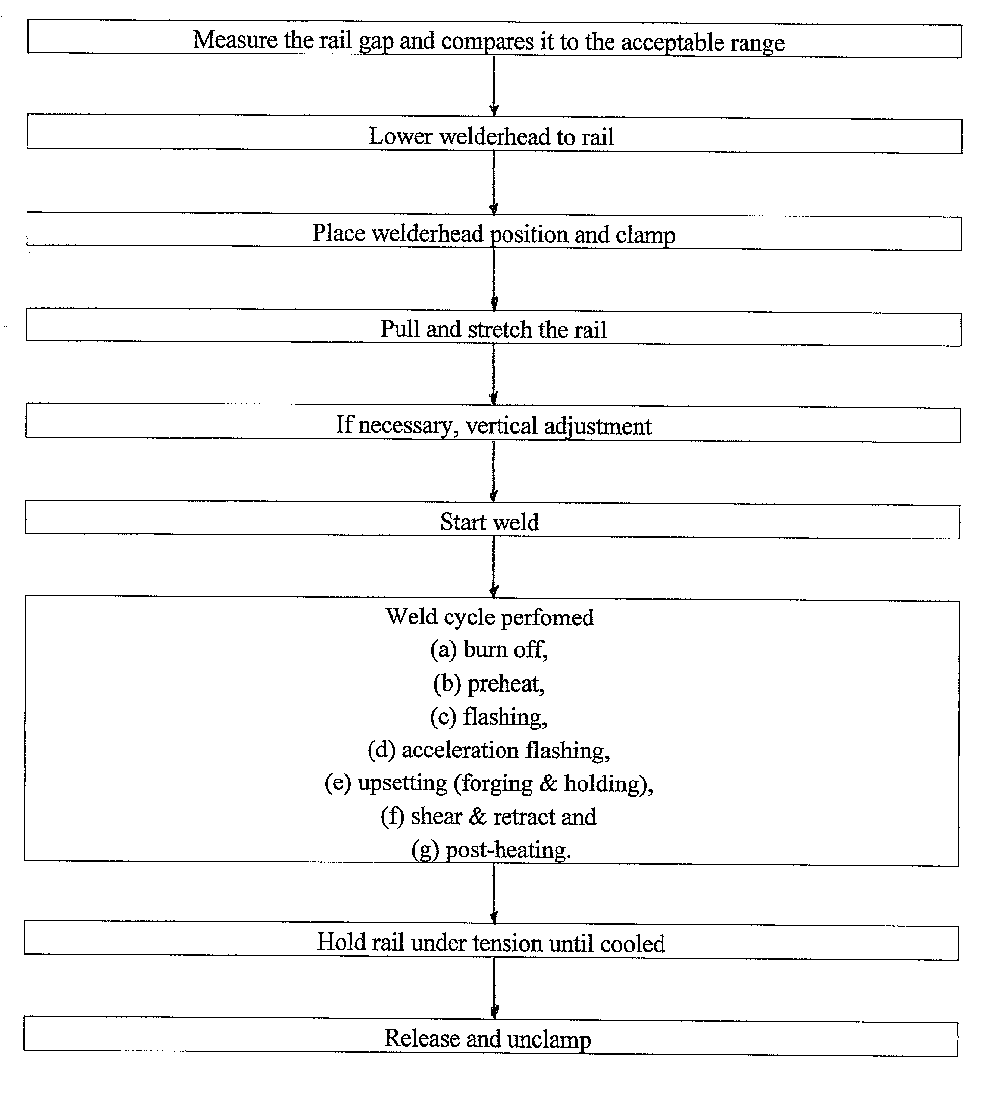
[0009] The welderhead uses a lever actuated shear die placed proximate the firebox of the welderhead. Unlike prior shear die mechanism actuators, the instant actuator enables the use of extremely strong arms on the welderhead and related structure and hydraulics that will enable the pulling of the rails themselves as well as the forging or upsetting operation. The improved shear die mechanism enables the jaws to remain fully clamped while the shear operation is accomplished. Thus, improved clearance and strength enable the elimination of many of the separate steps necessary for the combination of rail pulling, forging and shearing thereby enabling the performance of these functions smoothly and continually.

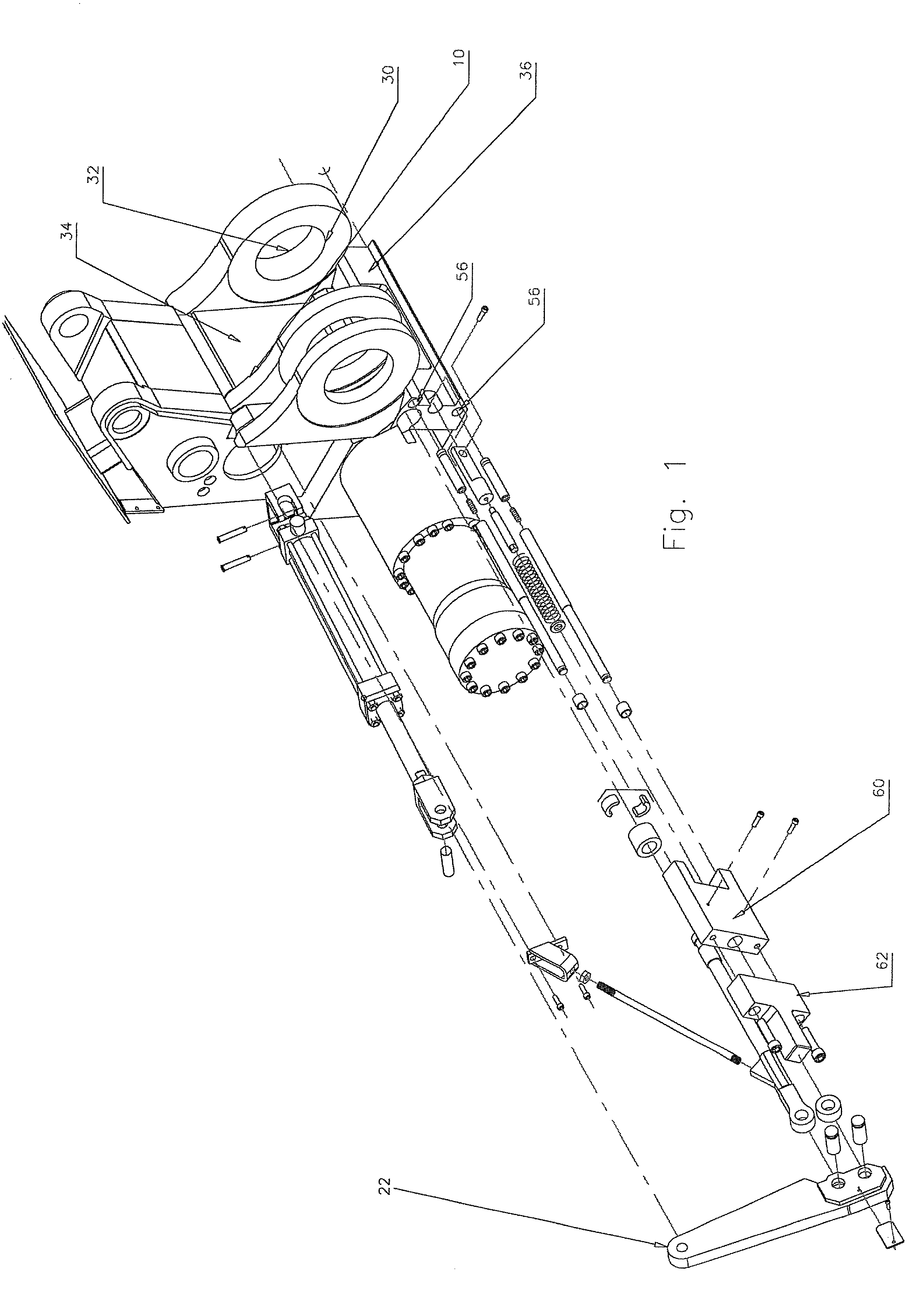
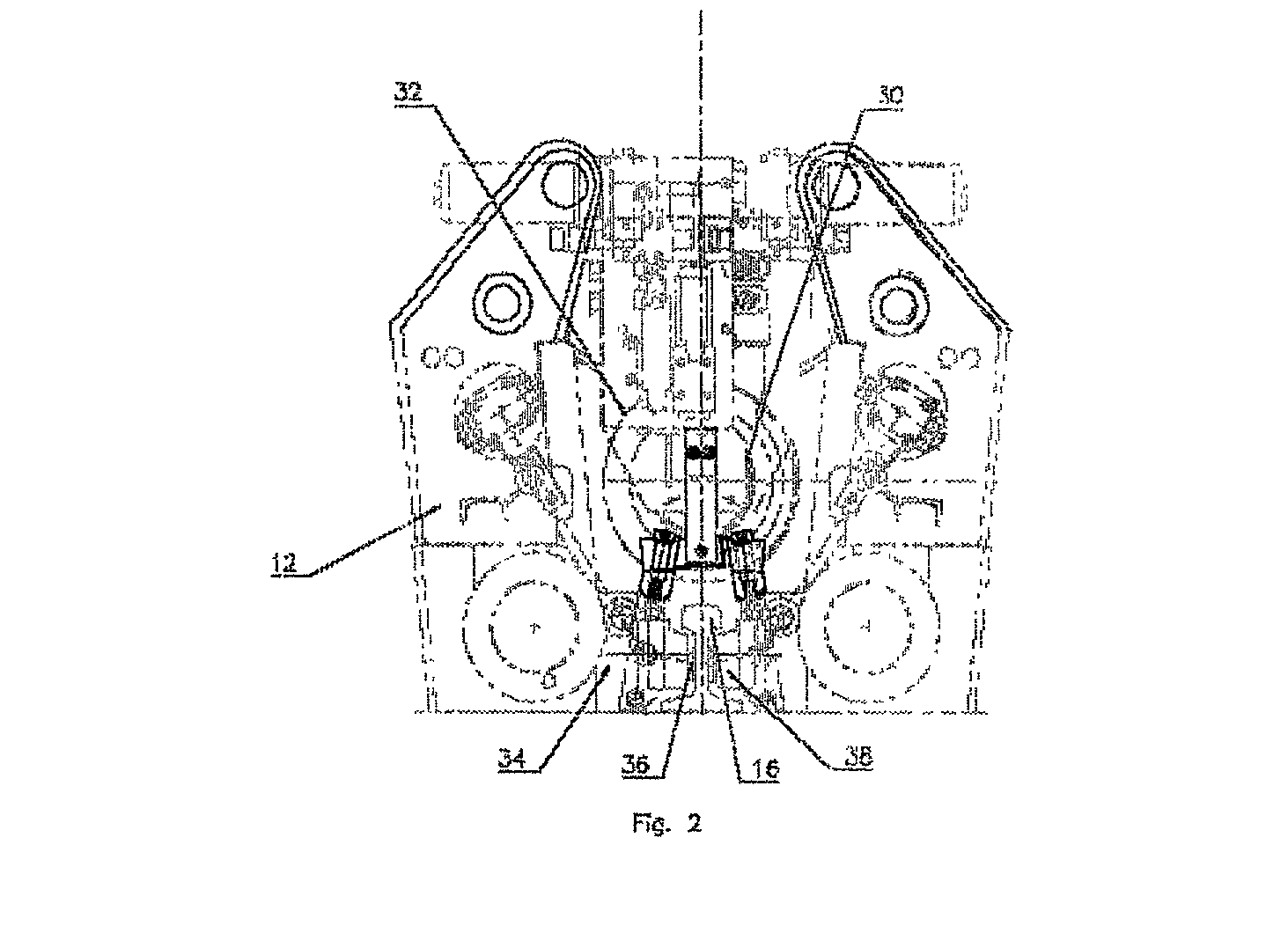
[0010] In accordance with one aspect of the present invention, a rail welderhead comprises two opposing pairs of quadrants constructed and arranged to close on adjacent rail sections and provide rail clamping by engagement of pads provided on the rail sections, the opposing pairs ...


PUM

PropertyMeasurementUnit
Tensionaaaaaaaaaa
Stretching forceaaaaaaaaaa

Abstract

A flash butt rail welding welderhead combines in a single unit, the ability for the three functions of rail pulling, flash butt forging and maintaining the "after forged" displacement without any change in platen position such that shearing may be accomplished in three stages, a single stage, multiple stages or a progressive stage, all while maintaining clamping and stretching force on the rails.

Description

CLAIM OF PRIORITY[0001] Priority is claimed based on our Provisional patent application Serial No. 60 / 226,232 filed Aug. 18, 2000 and entitled "RAIL WELDERHEAD SHEAR APPARATUS."[0002] 1. Field of the Invention[0003] An improved rail welderhead using extremely structurally strong quadrants, having large sections to yield high strength and the application of much larger forces in the single unit. This enables the single unit to perform tasks previously requiring separate pullers and forging-force welderheads. Because both rail stretching and tensioning and forging is done by the welderhead, it therefor becomes important to maintain tension while the weld cools. It is also desirable to shear the flash while the weld has not cooled substantially. Accordingly it is necessary to have a shear die set actuated using a high strength but compact mechanism requiring minimal clearance and operation within the area contained by the quadrants.[0004] In this manner a single welderhead can be used ...

Claims


Application Information

Patent Timeline
IPC IPC(8): B23K11/04
CPCB23K2201/26B23K11/04B23K2101/26
Inventor NORBY, ROBERT V.HUNZIKER, RENE A.
Owner HOLLAND CO
Why Eureka
Try Eureka