Communication connector with improved crosstalk compensation

a communication connector and crosstalk compensation technology, applied in the field of crosstalk compensation, can solve the problems of increasing noise to the neighboring conductive path pair, degrading return loss, and crosstalk due to capacitive and inductive couplings among closely spaced parallel conductors within the plug and/or jack, so as to improve communication channel performance, improve communication jack production efficiency/reliability, and improve communication channel performance

Active Publication Date: 2010-12-14
PANDUIT
View PDF63 Cites 92 Cited by
  • Summary
  • Abstract
  • Description
  • Claims
  • Application Information

AI Technical Summary

Benefits of technology

[0009]An advantage of at least one embodiment of the present invention is a compensation technology with a minimal amount of compensation capacitors.
[0010]Another advantage of at least one embodiment of the present invention is improved production efficiency / reliability of the communication jack.
[0011]Yet another advantage of at least one embodiment of the present invention is improved return loss in the communication jack.
[0012]Yet another advantage of at least one embodiment of the present invention is improved communication channel performance due at least in part to improved return loss in the communication jack.

Problems solved by technology

A concern with differential signals is electrical noise that is caused by neighboring differential conductive path pairs, where the individual conductors on each conductive path pair couple (inductively or capacitively) in an unequal manner that results in added noise to the neighboring conductive path pair.
In the communications industry, as data transmission rates have steadily increased, crosstalk due to capacitive and inductive couplings among the closely spaced parallel conductors within the plug and / or jack has become increasingly problematic.
The addition of these extra capacitors may degrade return loss and create issues in production where minor manufacturing variations in the capacitors lead to jack failures.

Method used


Image

  • Communication connector with improved crosstalk compensation
  • Communication connector with improved crosstalk compensation
  • Communication connector with improved crosstalk compensation

Examples


Embodiment Construction

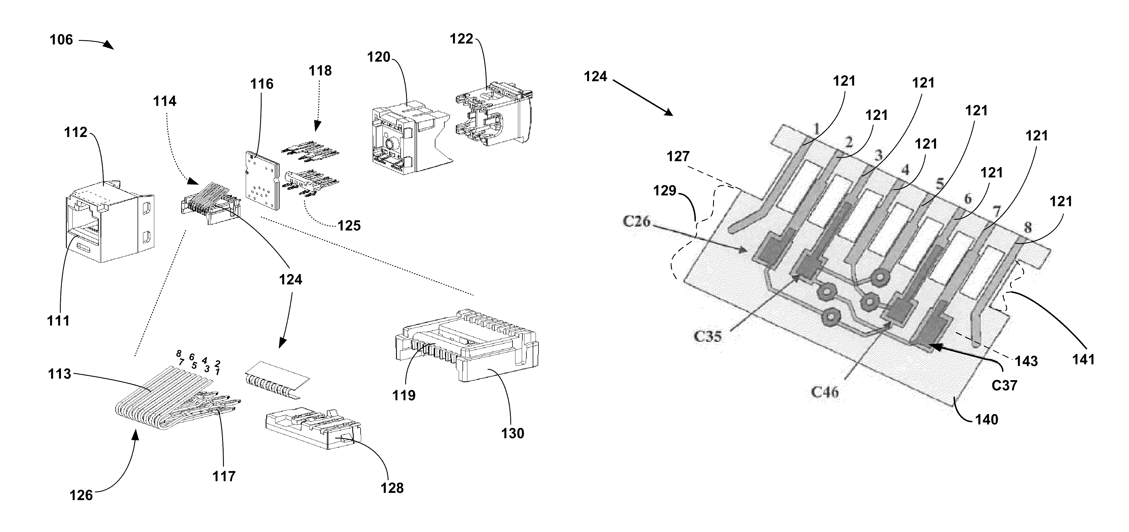
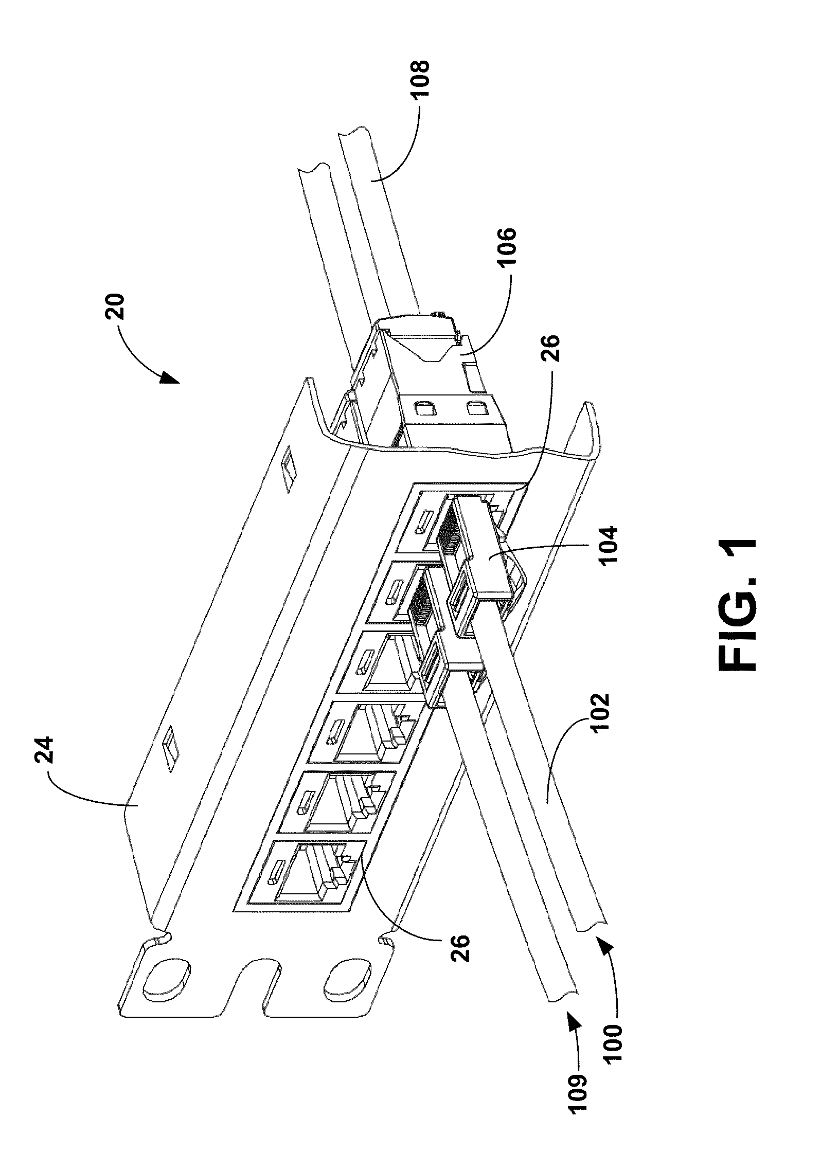
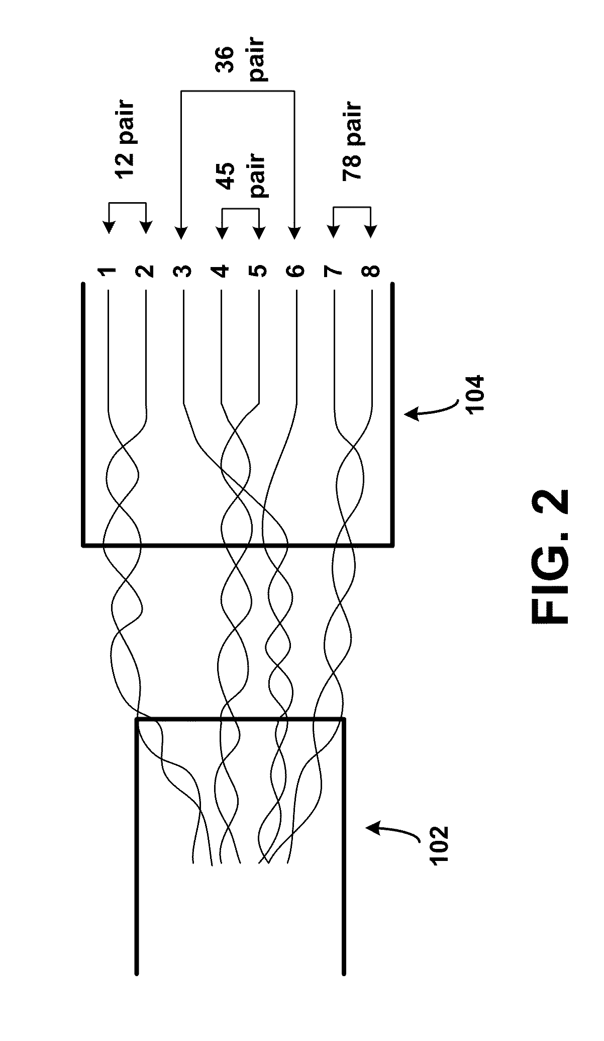
[0027]Referring to the drawings, and more importantly to FIG. 1, there is shown an electrical system 20 which includes a portion of a transmission channel 100 used to transmit data in the form of electrical signals. As shown from left to right, the portion of channel 100 may include a first cable 102, a communication plug 104, a communication jack 106, and a second cable 108, with the first cable 102 terminated to the communication plug 104 and the second cable 108 terminated to the communication jack 106. When the communication plug 104 and the communication jack 106 are mated, data may be transmitted between the first cable 102 (and any devices connected thereto) and the second cable 108 (and any devices connected thereto) via the mated plug 104 / jack 106 (i.e., the connectors). In one example, the first cable 102 and communication plug 104 may be part of a patch cable that connects a computing device (e.g., a personnel computer) to the communication jack 106, and the second cable ...


PUM


Abstract

A communication jack has a housing with a face having a plug receiving aperture. A plurality of conductive path pairs extends from corresponding plug interface contacts located at the plug receiving aperture to corresponding output terminals. A first circuit board is connected to the plug interface contacts and a second circuit board is connected to the plug interface contacts and the output terminals. The first circuit board has a first single stage of crosstalk compensation with opposite polarity of the crosstalk of a plug for a first combination of the conductive path pairs. The second circuit board includes a second single stage of opposite polarity crosstalk compensation for some of the conductive path pairs not compensated on the first circuit board. The stages cancel substantially all of the crosstalk caused by the plug, for the signal operating frequencies, for corresponding combinations of the conductive path pairs.

Description

FIELD OF THE INVENTION[0001]The present invention relates generally to crosstalk compensation, and more particularly, to crosstalk compensation in a communication jack.BACKGROUND OF THE INVENTION[0002]In an electrical communication system, it is sometimes advantageous to transmit data in the form of differential signals over a pair of conductive paths (i.e., a conductive path pair) rather than a single conductive path, where the transmitted signal comprises the voltage difference between the conductive paths without regard to the absolute voltages present. Each conductive path in a conductive path pair is capable of picking up electrical noise from outside sources, e.g., neighboring data lines, or other sources. Differential signals may be advantageous to use due to the fact the signals are less susceptible to these outside sources.[0003]A concern with differential signals is electrical noise that is caused by neighboring differential conductive path pairs, where the individual cond...

Claims


Application Information

Patent Timeline
Patent Type & Authority Patents(United States)
IPC IPC(8): H01R24/00
CPCH01R13/6625H01R13/6658H05K1/0228H01R13/6466H01R4/2425H05K1/118H05K1/147H05K1/162H05K2201/09172H05K2201/09672H05K2201/10189H01R24/64Y10S439/941H01R12/71H01R13/6633H01R24/00
Inventor STRAKA, FRANK M.TELLAS, RONALD L.
Owner PANDUIT
Why Eureka
Try Eureka