Method for detecting errors in a motor vehicle engine cooling system

a technology for engine cooling and errors, applied in the direction of machines/engines, mechanical equipment, instruments, etc., can solve the problems of not being able to distinguish between defects in the supply line or the display, and not being able to determine whether the thermostat valve or even the temperature sensor is defectiv

Inactive Publication Date: 2002-10-31
ROBERT BOSCH GMBH
View PDF0 Cites 27 Cited by
  • Summary
  • Abstract
  • Description
  • Claims
  • Application Information

AI Technical Summary

Problems solved by technology

Based on the resultant error message, however, it cannot be determined whether the thermostat valve or even the temperature sensor is defective.
Nor is it possible to make a distinction between defects in the supply line or the display.

Method used


Image

  • Method for detecting errors in a motor vehicle engine cooling system
  • Method for detecting errors in a motor vehicle engine cooling system
  • Method for detecting errors in a motor vehicle engine cooling system

Examples


Embodiment Construction

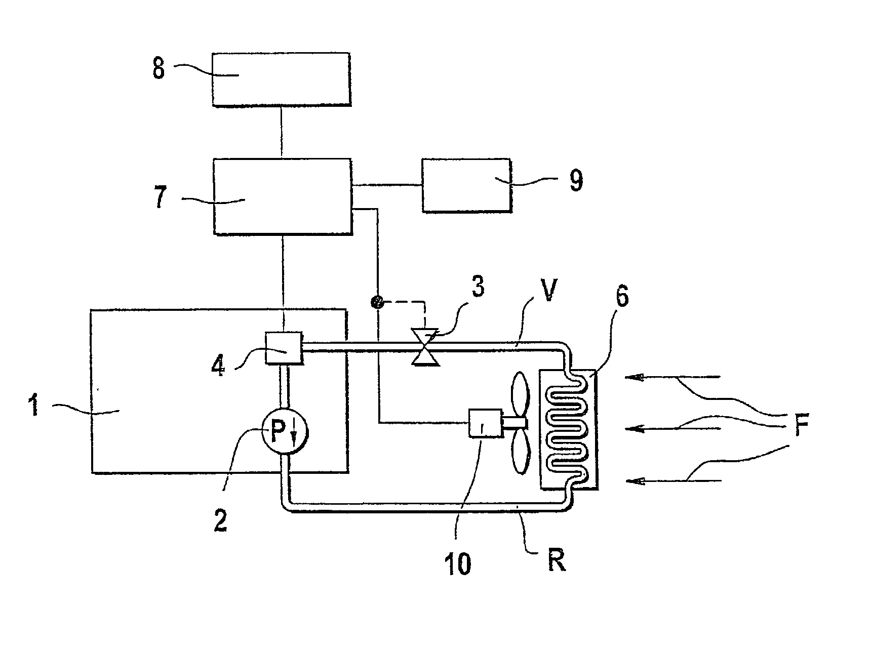
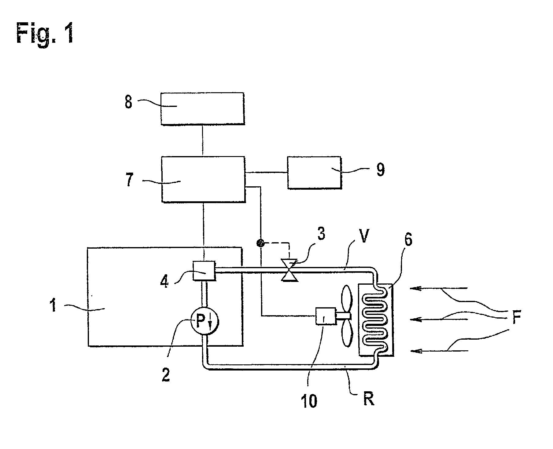
[0012] FIG. 1 shows, in greatly simplified form, a block diagram of a cooling circuit having an engine 1, in which the cooling water is directed through a radiator 6 using a circulation pump 2 by way of a supply line V and a return line R. A thermostat valve 3, which is preferably mechanically operated, opens or closes depending on the coolant temperature. It should be closed at a low temperature, while it opens wide at a high temperature, thereby allowing a greater cooling-water stream to flow in the direction of the radiator 6. For reasons of completeness, it is also pointed out that the cooling effect of the radiator 6 can be intensified using one or more cooling fans 10 and / or the air stream F. A temperature sensor 4 is provided in a suitable location (preferably on the engine block) in the cooling-water circuit and detects the momentary actual temperature of the cooling water. This measured value is fed to a computer 7 that controls the function of the cooling fan 10 using a pr...


PUM


Abstract

A method for detecting errors in a motor vehicle engine cooling system is proposed according to the invention, in which an algorithm is used to not only detect an error in the cooling system, but to also determine whether the thermostat valve or the temperature sensor are defective. Differentiated error detection is achieved in that a second temperature model band is calculated for the case in which the thermostat remains in the opened state. A first temperature model band is calculated for the case in which the cooling system is in order. By comparing the course of the curve for the measured actual temperature with the two temperature model bands, a selective diagnosis can be carried out and determine whether the temperature sensor or the thermostat valve is defective. No additional hardware expenditures are required.

Description

RELATED ART[0001] The invention is based on a method for detecting errors in a motor vehicle cooling system based on the general class of the primary claim. It is already known that the cooling-water temperature of a motor vehicle cooling system is controlled by opening and closing a thermostat valve. The temperature of the cooling water is measured by a temperature sensor and fed to a computer that uses an algorithm and the measured values for the actual temperature to calculate a first temperature model band. By comparing the actual temperature with the first temperature model band, error detection is then carried out. Based on the resultant error message, however, it cannot be determined whether the thermostat valve or even the temperature sensor is defective. Nor is it possible to make a distinction between defects in the supply line or the display. On the other hand, there are legal requirements, in the United States, for example, which state that a defective cooling-water ther...

Claims


Application Information

Patent Timeline
Patent Type & Authority Applications(United States)
IPC IPC(8): F01P7/16F01P11/14F01P11/16
CPCF01P11/14F01P11/16F01P2023/00F01P2023/08F01P2031/22F01P2025/64F01P2031/00F01P2031/20F01P2025/62
Inventor KASTNER, FRANKWILTSCH, PETER
Owner ROBERT BOSCH GMBH
Why Eureka
Try Eureka