Foldable scaffold device

a scaffolding and folding technology, applied in the direction of scaffold accessories, constructions, building aids, etc., can solve the problem of the workman in the scaffold floor being exposed to danger

Inactive Publication Date: 2002-10-31
ONO TATSUO
View PDF0 Cites 19 Cited by
  • Summary
  • Abstract
  • Description
  • Claims
  • Application Information

AI Technical Summary

Problems solved by technology

Disadvantage of the known structures is that they are inclined in case of attaching a scaffold device by a strong threading force of said nut, because rear structures are pulled backwardly by a reaction of said threading.
And the scaffold device is rotated to a direction such as pivo

Method used


Image

  • Foldable scaffold device
  • Foldable scaffold device
  • Foldable scaffold device

Examples


Embodiment Construction

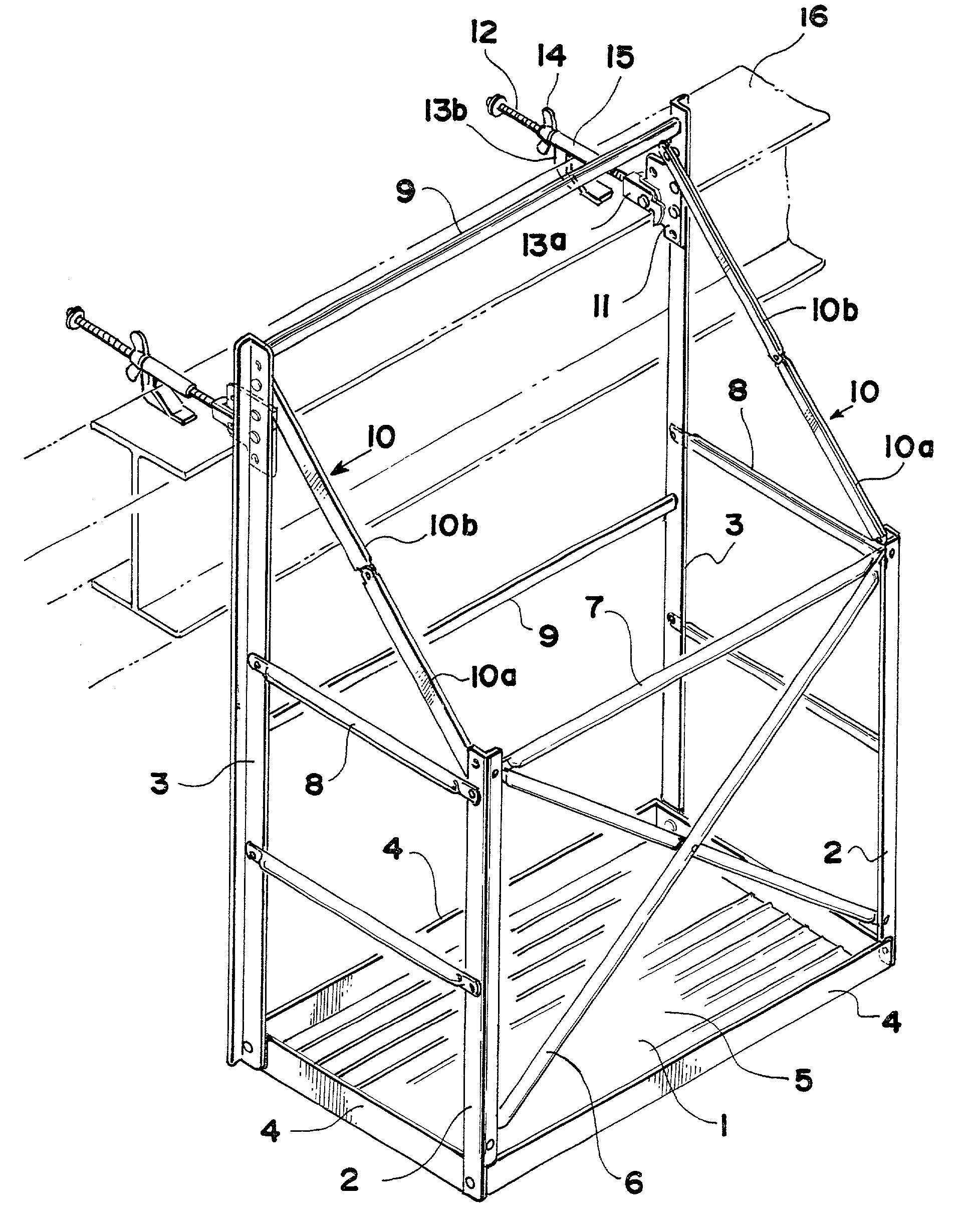
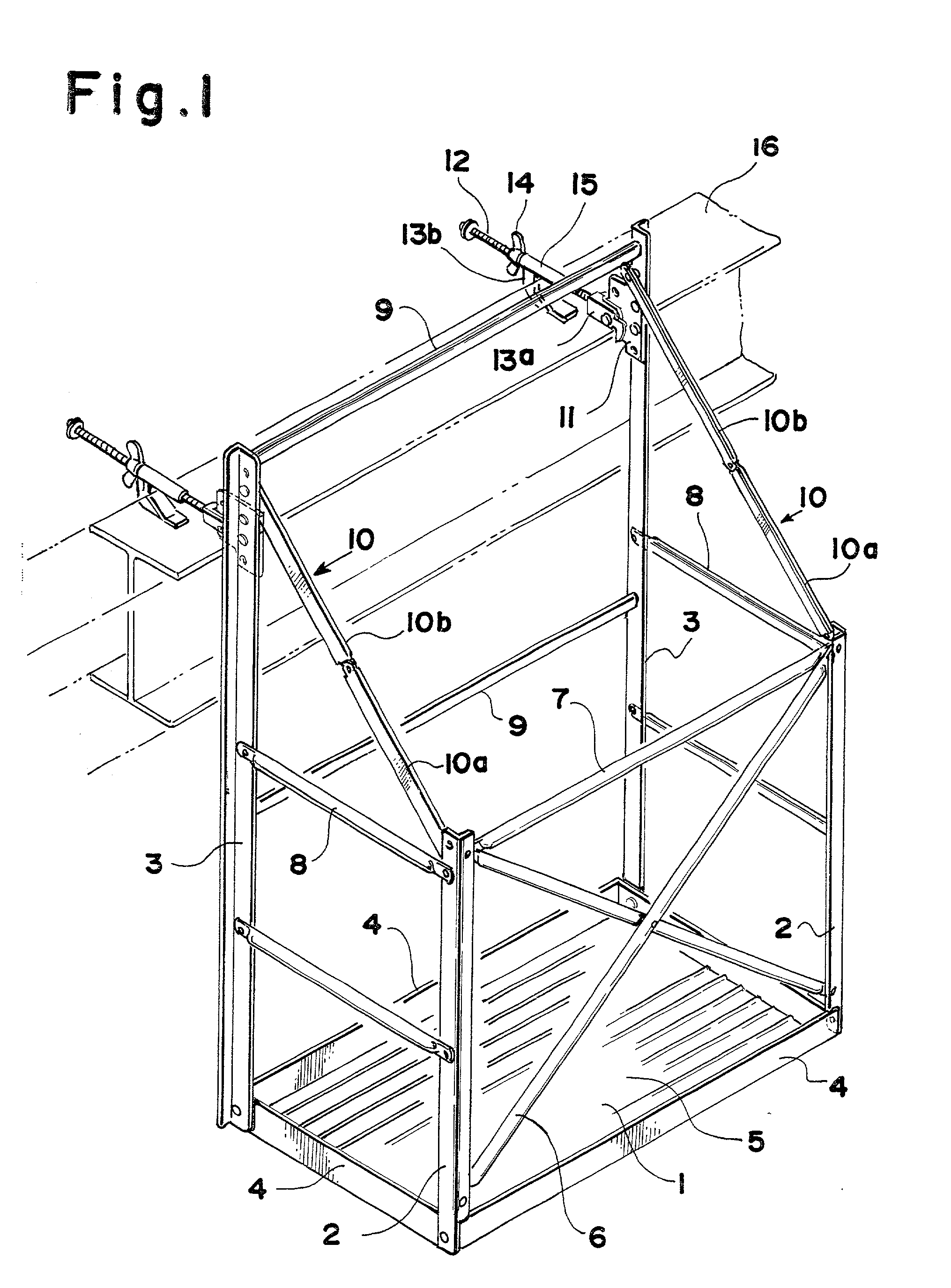
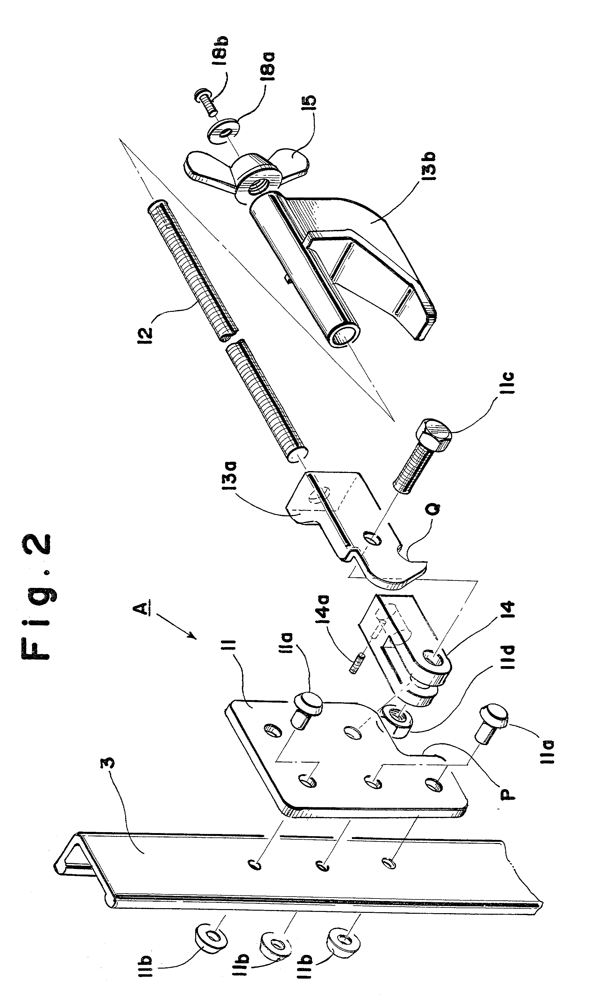
[0019] In accordance with the invention there is provided an erectable and transportable scaffold cage which comprises a rear frame structure may up of elongated side struts 3, 3 which are interconnected by a plurality of horizontal transversely extending brace beam 9. A front frame structure comprising side angled members 2, 2 which are shorter than the rear angled 3, 3 and one or more cross members 7 and diagonal bracing 6 is hinged to the rear structure through a plurality of parallel lateral bracing members or supports 8 which are articulated at their respective ends to the respective front and rear structures. The front structure may be folded into juxtaposition with the rear structure as shown in FIG. 5 or it may be erected to the position in FIG. 1 in which the reinforcing plate 1 extends substantially horizontally. The reinforcing plate 1 is provided with a plurality of bolt portions which are pivotally connected to the respective struts 2, 2 and 3, 3 at their lower ends. Th...


PUM


Abstract

An erectable and transportable scaffold device adapted to be engaged on and supported on a support beam comprises front and rear frame structures which are pivotally interconnected by means of parallel side braces which are connected between the frame structures. A scaffold plate is pivotally connected to the lower ends of each of the front and rear frames. And the front frame is pivotal outwardly from the rear structure to form a cage within the front and rear structures and the side braces having a floor formed by a scaffold plate. The plate has upright bottom edges which fit flush against the insides of an angle member forming the sides of the front frame structure so that it facilitates the holding of the structure in an erected cage forming position. A flexible or foldable member such as a chain or so is connected between the upper ends of each side of the front structure to the upper ends of each side of the rear structure. The rear structure also carries a rotatable hinge or an universal joint connected to a bolt having a front pawl and a rear pawl which is slidable therealong and which may be engaged against a support structure such as an I-beam by threading a wing nut onto the bolt behind said rear pawl to lock it in position.

Description

[0001] 1. Field of the Invention[0002] This invention relates in general to the construction of scaffolding device and in particular to an improved scaffold which includes front and rear structures which are pivotally interconnected by parallel side braces so that the front structure may be suspended by means of a flexible element outwardly from the rear structure to form a cage.[0003] And further the rear structure of the scaffolding device is fixed and settable safely, reliably and firmly to a support structure such as an I-beam in a place to construct.[0004] 2. Description of the Prior Art[0005] The invention relates to the construction of a foldable scaffold device which is particularly useful in the erection of buildings or the construction of ships, etc. The foldable scaffold device of prior art is well known as shown in The U.S. Pat. No. 4.029.173.[0006] And known scaffold device is secured in position on a supporting structure such as a beam through a fitting means. Said fit...

Claims


Application Information

Patent Timeline
IPC IPC(8): E04G3/00E04G3/22E04G5/04
CPCE04G3/00E04G5/04E04G3/22E04G5/045
Inventor ONO, TATSUO
Owner ONO TATSUO
Why Eureka
Try Eureka