Method for controlling quality and condition on the basis of thermal imaging

a technology of thermal imaging and quality control, applied in the direction of optical radiation measurement, instruments, material flaw investigation, etc., can solve the problems of easy disassembly and use of thermal image information, and easy disassembly of transient phenomena which may only occur recurrently, so as to reduce the intensity, efficient eliminate random noise, and good sensitivity

Inactive Publication Date: 2002-11-14
METSO AUTOMATION OY
View PDF7 Cites 24 Cited by
  • Summary
  • Abstract
  • Description
  • Claims
  • Application Information

AI Technical Summary

Problems solved by technology

However, the above-presented prior art methods utilizing a thermal camera involve the problem that the information contained in the thermal images is primarily analyzed by the user viewing the images.
For this reason, some of the information contained in the thermal images may also easily remain unutilized.
Furthermore, the solutions of prior art involve the problem that transient phenomena which may also occur only recurrently are easily disregarded by the user.
In particular, phenomena which are very low in intensity and occur only recurrently in thermograms are very difficult to be detected by the human eye.
The first-mentioned method has the disadvantage of high equipment costs caused by the cameras, whereas the latter method has the disadvantage of slowness and poor repeatability of the manual measurements.

Method used


Image

  • Method for controlling quality and condition on the basis of thermal imaging
  • Method for controlling quality and condition on the basis of thermal imaging
  • Method for controlling quality and condition on the basis of thermal imaging

Examples


Embodiment Construction

to be explicated will examples will more clearly illustrate, for anyone skilled in the art, advantageous embodiments of the invention as well as advantages to be achieved with the invention in relation to prior art.

[0021] In the following, the invention will be described in more detail with reference to the appended drawings, in which

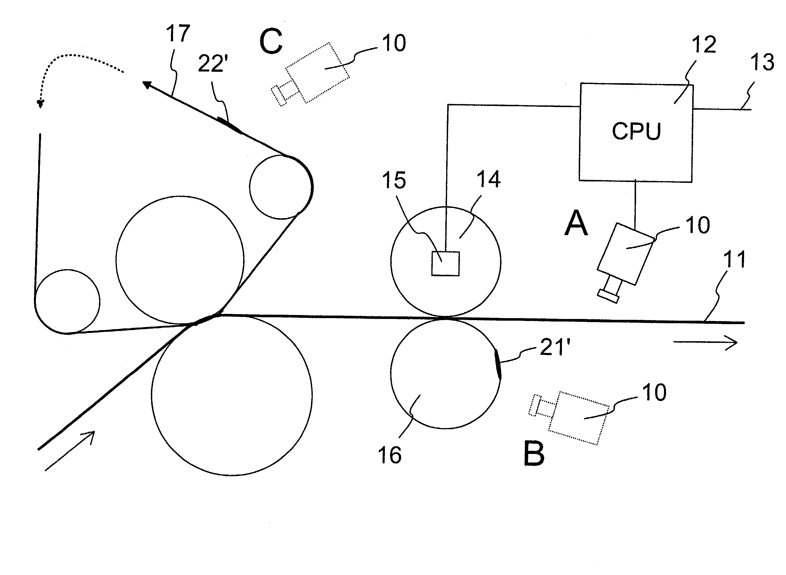
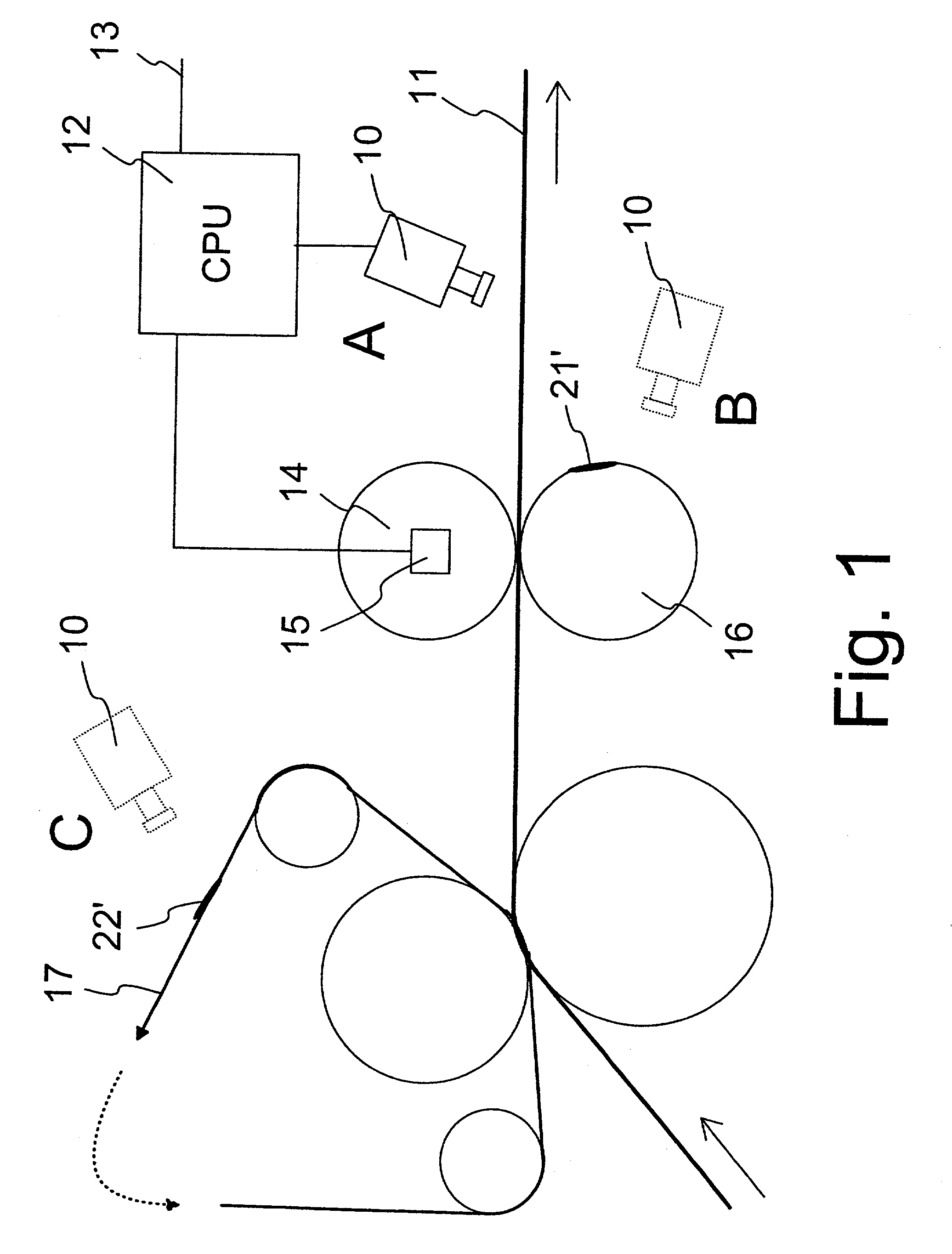
[0022] FIG. 1 shows some possible embodiments of the invention in principle,

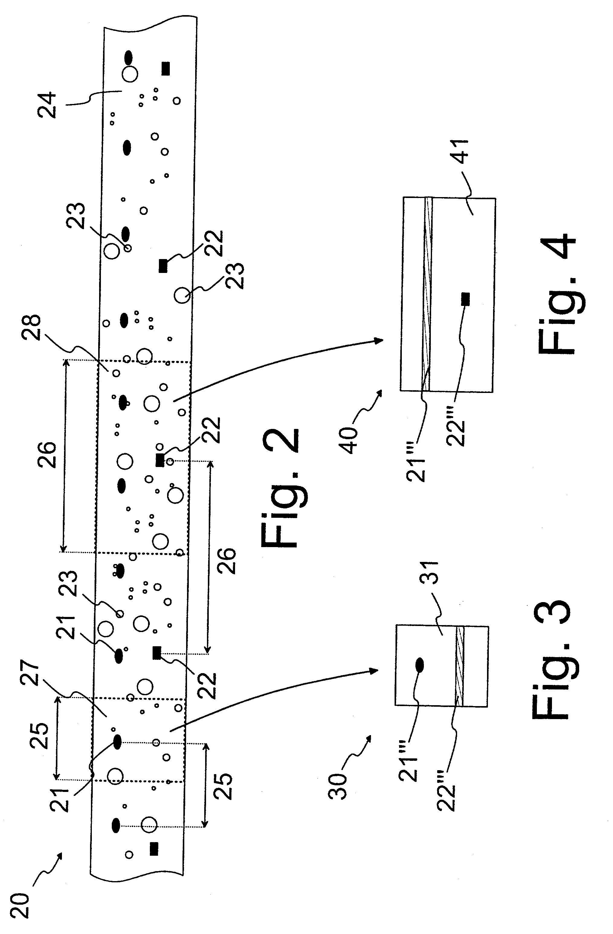
[0023] FIG. 2 illustrates a continuous thermal chart formed according to the invention in principle,

[0024] FIG. 3 shows, in principle, a matched thermal chart obtained from the continuous thermal chart of FIG. 2 by averaging across a given interval, and

[0025] FIG. 4 shows, in principle, a matched thermal chart obtained from the continuous thermal chart of FIG. 2 by averaging across another interval.

[0026] FIG. 1 shows, in principle, some possible embodiments of the invention which correspond to different positions A, B and C of a thermal camera indicated in FIG. 1.

[0027] A therm...


PUM

PropertyMeasurementUnit
infrared wavelength rangeaaaaaaaaaa
speedaaaaaaaaaa
operating wavelength rangeaaaaaaaaaa

Abstract

The invention relates to a method in the process of manufacturing and / or finishing a fibre web (11), in which method said continuous and moving web (11), and / or a moving means (16, 17) related to the processing of the web (11), is monitored by one or more thermal cameras (10) of the infrared range or a corresponding detector / detectors for the purpose of controlling the quality or condition. According to the invention, a substantially continuous two-dimensional thermal image or continuous thermal chart (20) of an object (11, 16, 17) being monitored and in a propagating and / or rotating movement is formed by said detector / detectors in a time-resolved manner and in synchronization with the movement of the object (11, 16, 17) in the direction of the movement. To determine the properties of the object (11, 16, 17) and / or to detect defects in the object from the continuous thermal chart (20), local deviations and / or discontinuities (21, 22) in the temperature, particularly in the direction of movement, are detected, and the cause of said deviations and / or discontinuities (21, 22) is identified on the basis of the periodicity of said phenomena in the direction of movement.

Description

[0001] The invention relates to a method for controlling quality and condition on the basis of thermal imaging, to be used in connection with processes of manufacturing and / or finishing a continuous fibre web.BACKGROUND OF THE INVENTION AND PRIOR ART[0002] With improved technology and usability of thermal cameras, they are being increasingly used in various industrial condition and quality control applications. Conventionally, thermal imaging has been used for monitoring the condition of various apparatus components. Typical uses have included, for example, the monitoring of the condition of various engines and bearings at intervals. By means of thermal imaging, defects in components can be detected in a contactless manner, for example as an increase in the surface temperatures of the components.[0003] In paper industry, thermal imaging has also been applied to measure properties of the fibre web to be manufactured and / or processed, various rolls, as well as reels formed of the web,...

Claims


Application Information

Patent Timeline
Patent Type & Authority Applications(United States)
IPC IPC(8): D21G9/00G01N21/892G01N25/72G01N33/34
CPCD21G9/0027D21G9/0036G01N33/346G01N25/72G01N21/8922
Inventor KOMULAINEN, ANTTIJUPPI, KARIAIMONEN, PERTTI
Owner METSO AUTOMATION OY
Why Eureka
Try Eureka