Eureka AIR delivers breakthrough ideas for toughest innovation challenges, trusted by R&D personnel around the world.

Retractable roller mechanism

Inactive Publication Date: 2002-11-21
CHERUKURI HEMA
View PDF0 Cites 1 Cited by
  • Summary
  • Abstract
  • Description
  • Claims
  • Application Information

AI Technical Summary

Benefits of technology

[0005] It is an object of the present invention to provide an improved retractable roller mechanism that can be operated conveniently by the normal forces that are applied to the item on which the roller mechanism is mounted, without the requirement of an individual having to access the roller mechanism itself.
[0006] It is a further object of the present invention to provide a retractable roller mechanism wherein the roller is automatically retracted into and and in an inoperative state by a exerting a force that is greater than the normal weight of the item from the item to the support surface, allowing the item to assume a static or stationary position for the period of time in which the force is continuously applied.
[0007] Still another object of the present invention is to provide a retractable roller mechanism wherein the roller is automatically placed into an operative state, and permitting free movement of the item along the support surface when the force from the item to the support surface is equal to the normal weight of the item.
[0008] Yet another object of the present invention is to provide a retractable roller mechanism of simple non castor construction that allows only bi-directional movement of the item while the roller mechanism is in the operative state.
[0010] It is yet another object of the present invention to provide a retractable roller mechanism that while in an operative state or in inoperative state will result in none or minimal damage to the support surface.
[0011] It is further yet another object of the present invention to provide a retractable roller mechanism that is constructed of a minimum number of parts for ease of manufacture and lower unit costs.

Problems solved by technology

Previous approaches to this problem have often resulted in complex caster mechanisms that required the item to be lifted in order to actuate the caster into the previously mentioned first operating state from the second operating state or vice versa.
The problem with this approach was that it required the item to be lifted, which is unsatisfactory because the desire to avoid lifting the item is the reason for providing roller mechanisms in the first place.
Even if a particular item is not all that heavy, the size and bulk of the item usually makes it difficult for an individual to simultaneously lift the item and operate the roller mechanism to change the operating state, in addition most items have multiple roller mechanisms which require a single individual to lift the item multiple times at different locations.
The aforementioned complex caster mechanisms have sometimes included jacks, in which the item can be raised and lowered to effectuate the roller mechanism changing its operating state, however, these mechanisms were still difficult to use for two reasons.
First, if the item was located in a confined area or space, the jack mechanism was difficult to access, and secondly, the location of the jack, typically being on the bottom of the item could be difficult for an individual to be able to reach to the jack mechanism while simultaneously attempting to lift the item.
The problem with the spherical roller is that it operated at a close clearance with the socket assembly and was prone to ingesting foreign material into this close clearance, such as carpet fibers, when the spherical roller was moving across the support surface which caused a high degree of a frictional resistance to the spherical roller rotating.
This resistance to rotation by the spherical roller made it difficult to move the item along the support surface.
Another problem with the spherical roller was that it had a small contact area with the support surface which increased the unit loading that the spherical roller placed upon the support surface from the weight of the item, this in turn increased the likelihood of damage to the support surface from the spherical roller.

Method used


Image

  • Retractable roller mechanism
  • Retractable roller mechanism
  • Retractable roller mechanism

Examples


Embodiment Construction

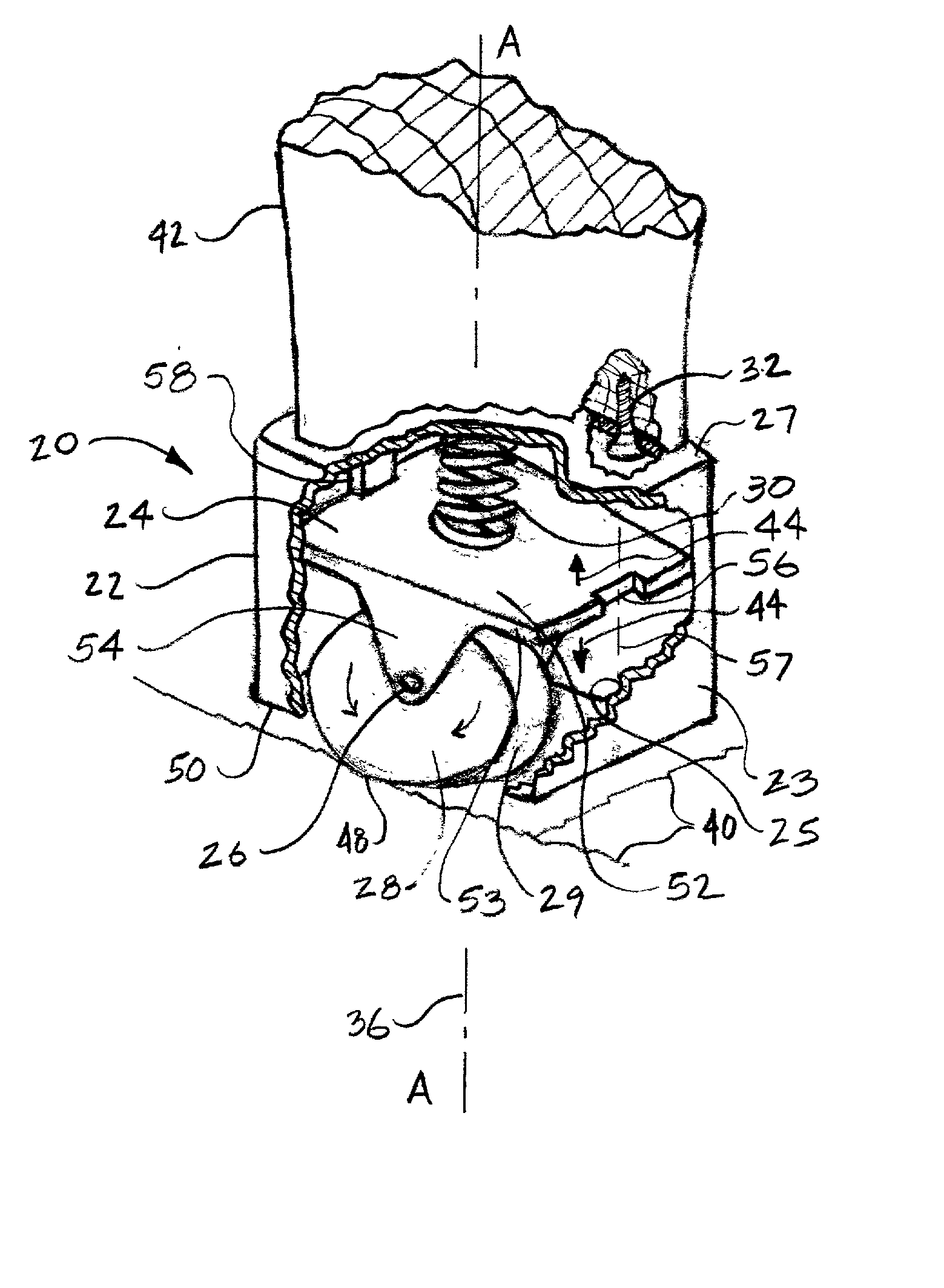
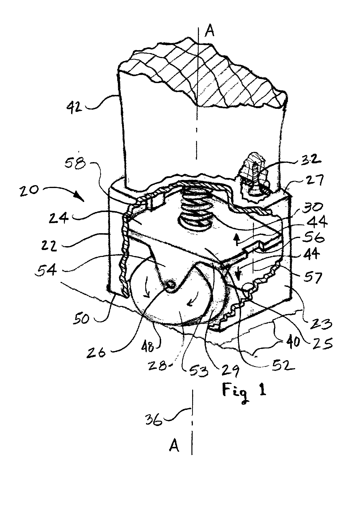
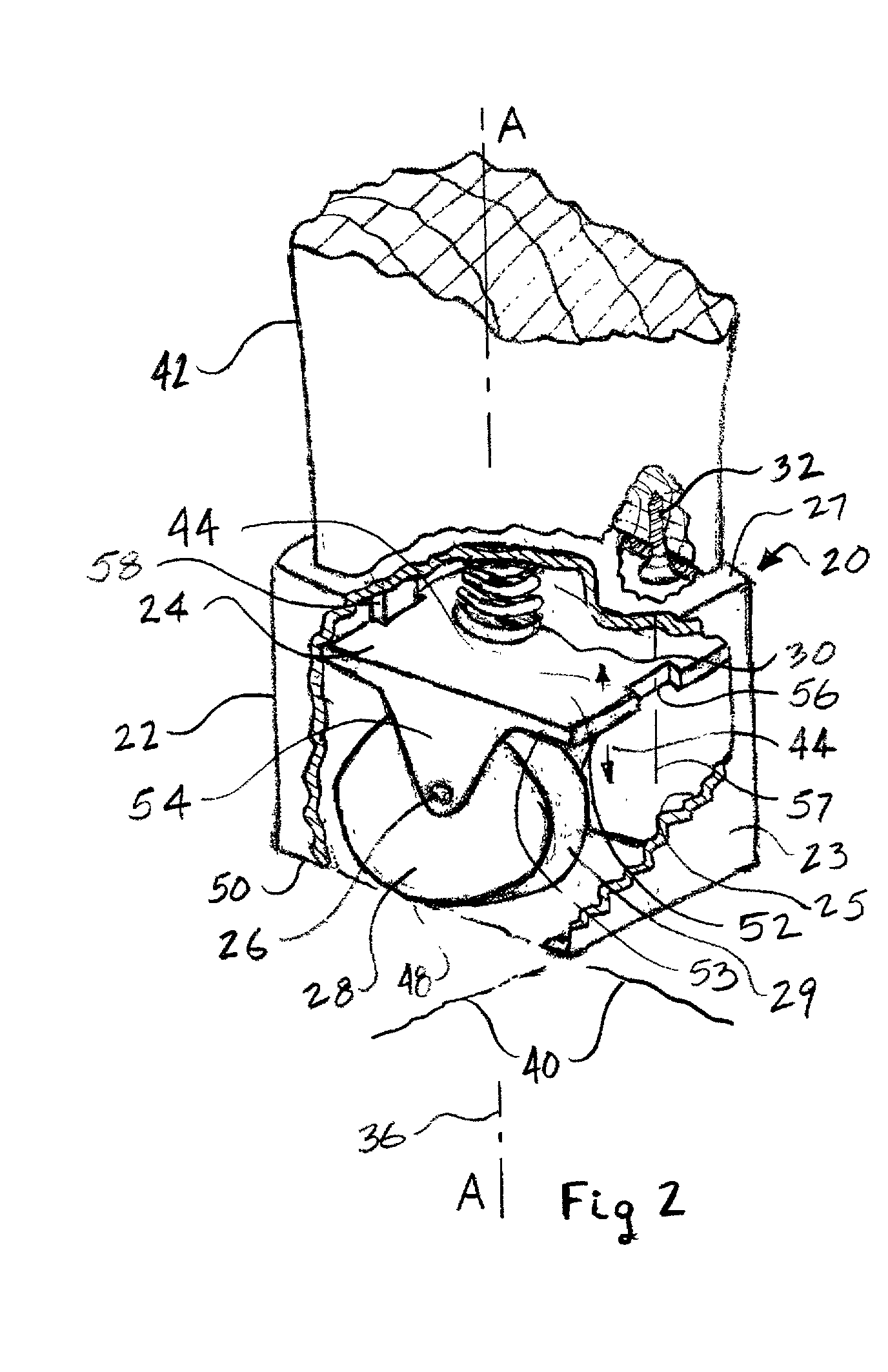
[0063] Referring to FIGS. 1 and 2 for the preferred embodiment, a method is given for using the retractable roller mechanism 20 for statically supporting an item 42 upon the support surface 40 with the retractable roller mechanism 20 in an inoperative state and supporting the item 42 to roll along the support surface by use of the retractable roller mechanism 20 in an operative state. Item 42 will typically be adpated toward having two operative states being desired by the individual in using the item 42, necessitating that the item 42 have its weight increased in a static position. The first state or operative state is where it is desired to have the item 42 be moveable along a support surface 40 to a desired position, where an an individual provides the motive force to move the item across the support surface 40, once the desired position is obtained then the individual will quit providing a motive force to item 42, allowing item 42 to be statically positioned at its desired locat...


PUM


Abstract

An improved retractable roller mechanism 20 and method for statically supporting an item 42 upon a support surface 40 in an inoperative state and supporting the item 42 to roll along the support surface 40 in an operative state. The retractable roller mechanism 20 includes a housing 22, a roller frame 24 that is slideably engaged with the housing 22, a spring 30, and a roller 28. The roller frame 24 has reciprocative movement relative to the housing 22, such that the frame 24 has an inoperative position state where the frame 24 is retracted allowing the housing 22 to rest on and statically contact the support surface 40 and an operative position state where the frame 24 is extended such that the housing 22 is not in contact with the support surface 40 allowing the item 42 to roll along the support surface 40.

Description

[0001] The present invention generally relates to mechanisms that act to support an item while at the same time allowing the item to move across a support surface. In particular, the present invention relates to using a retractable roller mechanism that provides a static support upon the support surface when the item, such as an article of furniture has a relatively high force towards the support surface causing the roller mechanism to retract, when the item has a relatively lower force towards the support surface the roller mechanism automatically separates the static support from the support surface thereby allowing a roller to freely move the item along the support surface.BACKGROUND OF INVENTION[0002] There has long been a desire to move large, bulky, and unwieldy items easily across a support surface with a minimum of effort while at the same time having the item not be unstable along the support surface during the times when it is desired that the item not to be easily moved a...

Claims


Application Information

Patent Timeline
IPC IPC(8): B60B33/06
CPCB60B33/0005B60B33/0018B60B33/0039B60B33/0049B60B33/0063Y10T16/1937B60B33/063Y10T16/212Y10T16/364Y10T16/209B60B33/045
Inventor CHERUKURI, HEMA
Owner CHERUKURI HEMA
Why Eureka
Eureka Blog
Learn More