
Damped valve

a technology of a valve element and a valve body, which is applied in the direction of machines/engines, liquid fuel engines, positive displacement liquid engines, etc., can solve the problems of damping the motion of the valve element, and achieve the effect of reducing the noise level of the machine, vacuum pumping, and running more quietly

Inactive Publication Date: 2002-11-21
BOC GRP INC
View PDF0 Cites 6 Cited by
  • Summary
  • Abstract
  • Description
  • Claims
  • Application Information

AI Technical Summary

Benefits of technology

[0009] The valve also has a damping piston attached to the valve element. Preferably, the piston projects in a direction away from the valve seat. A damping chamber is provided within which the piston is slidably received. The piston moves within the chamber along a path of travel extending toward and away from the valve seat. The damping chamber has an orifice which is small relatively to the cross-sectional area of the piston. The orifice is positioned along the path of travel away from the valve seat. The piston forces fluid within the chamber through the orifice and thereby damps motion of the valve element as the piston moves along the path of travel away from and toward the valve seat.
[0014] It is still another object of the invention to provide a damped valve which effects a reduction in the noise level of a machine into which the valve is incorporated.
[0015] It is again another object of the invention to provide a damped valve which allows a vacuum pump to run more quietly.

Problems solved by technology

The piston forces fluid within the chamber through the orifice and thereby damps motion of the valve element as the piston moves along the path of travel away from and toward the valve seat.

Method used


Image

  • Damped valve
  • Damped valve
  • Damped valve

Examples


Embodiment Construction

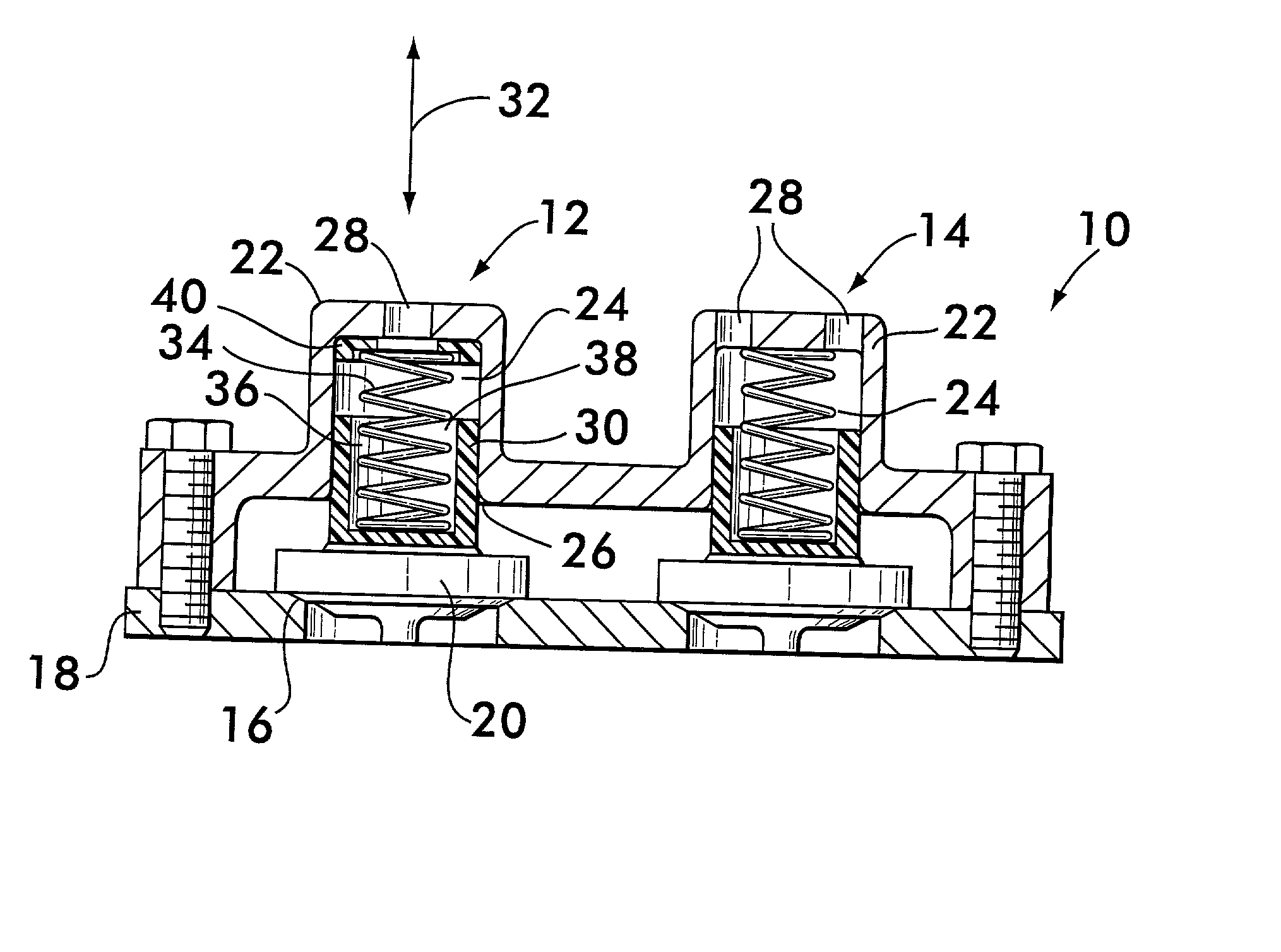
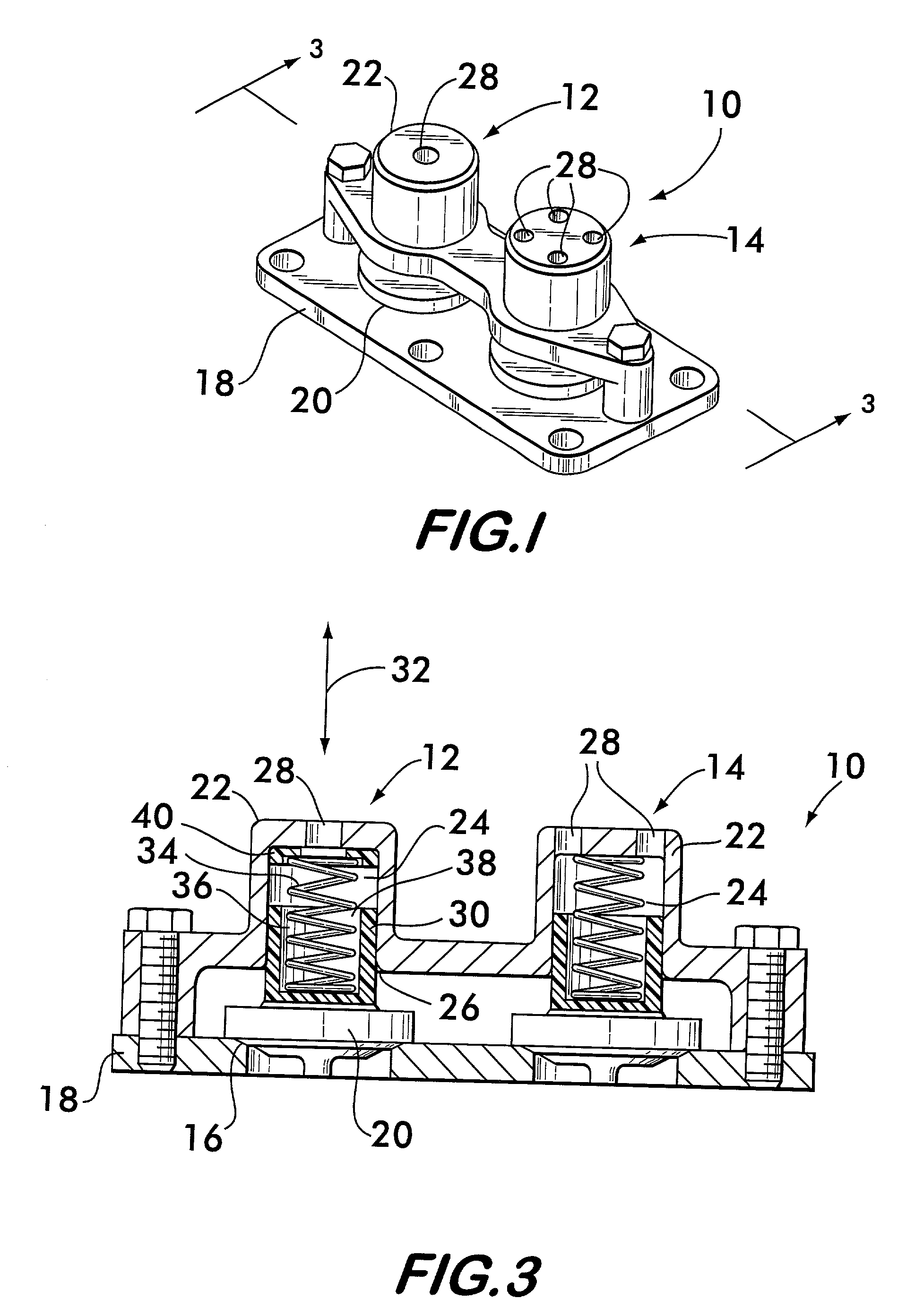
[0021] FIG. 1 shows a poppet valve assembly 10 comprising two embodiments of damped poppet valves 12 and 14 respectively. Valve 12 is described below in detail, valve 14 being also described to explain the differences between the embodiments.

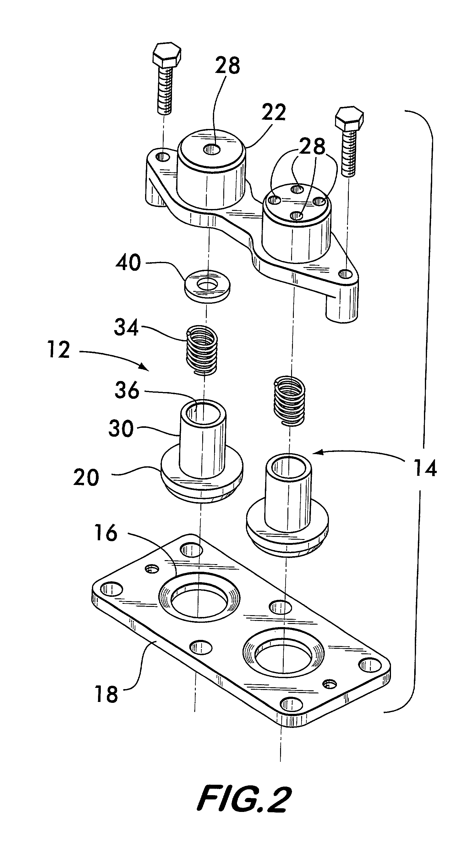
[0022] As shown in FIG. 2, valve 12 has a valve seat 16, preferably formed as a chamfered surface in a base plate 18 used to mount the valve assembly 10 onto a machine, such as a vacuum pump as shown in FIG. 4. A valve element 20 is movable substantially perpendicularly to seat 16 into and out of sealing engagement with the seat to effect opening and closing of the valve. FIG. 3 shows the valve element 20 in sealing engagement with the valve seat 16.

[0023] As further seen in FIGS. 2 and 3, a housing 22 is positioned in spaced relation to the seat 16. The housing defines an elongated damping chamber 24 with an opening 26 located at one end, preferably facing seat 16, and an orifice 28 at the other end. (Valve 14 shows an alternate valve embodimen...


PUM


Abstract

A damped poppet valve is disclosed. The valve has a valve element movable into and out of engagement with a valve seat to open and close the valve. A damping piston attached to the valve element is slidably received within a damping chamber along a path of travel toward and away from the valve seat. The chamber has an orifice which is small relatively to the cross-sectional area of the piston. The piston forces fluid through the orifice as it moves along the path of travel, thereby damping motion of the valve element.

Description

[0001] This invention concerns valves whose action is damped to reduce noise of machinery operation and especially damped poppet valves used in vacuum pumps.[0002] Valves are essential components of many machines such as pumps, engines, turbines and automatic transmissions and are the heart of almost every pneumatic or hydraulic device. The dynamic characteristics of certain valves, such as poppet valves, which open and close automatically in response to pressure differentials, may substantially affect the overall operation and performance of the machine of which they are a part.[0003] Poppet valves typically comprise a seat, a valve element which is movable into and out of sealing engagement with the seat to effect closing and opening of the valve and a biasing member, such as a spring, which biases the valve element into engagement with the seat. The valve element is not moved by an actuator, but is free floating and therefore able to open in response to a pressure differential ac...

Claims


Application Information

Patent Timeline
Patent Type & Authority Applications(United States)
IPC IPC(8): F04B39/10F04C29/12F16K15/02F16K15/06F16K47/02
CPCF04B39/102F04C29/126F16K47/023F16K15/066F16K15/026Y10T137/785F16K47/0111F16K15/063
Inventor CEROVICH, CHRISTOPHER J.
Owner BOC GRP INC
Learn More