Modular roller conveyor system

a conveyor system and module technology, applied in the field of conveyor systems, can solve the problems of high manufacturing cost, high production cost, high labor intensity, etc., and achieve the effect of inexpensive replacement of roller assemblies

Inactive Publication Date: 2003-01-02
VALIANT CO LTD
View PDF0 Cites 17 Cited by
  • Summary
  • Abstract
  • Description
  • Claims
  • Application Information

AI Technical Summary

Benefits of technology

[0013] Unlike the previously known roller conveyor systems, since the vertical supports in both the first pair of vertical supports and second pair of vertical supports are secured together at a user selected spacing, the width of the roller conveyor system can be easily varied to accommodate articles of different widths. Furthermore, the spacing between the rails may be easily modified at a subsequent date by merely adjusting the spacing between the first pair of vertical supports and second pair of vertical supports. In this event, relatively inexpensive replacement of the roller assemblies to accommodate the new conveyor width may be required.

Problems solved by technology

A primary disadvantage of this type of previously known industrial roller conveyor system is that each roller conveyor system has been custom designed and manufactured in dependence upon the particular type and size of article to be conveyed along the conveyor system.
While these previously known conveyor systems have proven satisfactory in operation, they are necessarily expensive to manufacture.
This high cost of manufacturing such previously known roller conveyor systems results in large part from the necessity that each roller conveyor system must be custom designed in accordance with the load conveyed.
Such custom design of these previously known roller conveyor systems necessarily entails increased engineering costs and highly skilled, and thus highly paid, assembly workers.
A still further disadvantage of these previously known roller conveyor systems is that, since each roller conveyor system is custom designed for a predetermined article, the roller conveyor system cannot be adapted for articles of different sizes, at least not articles of a larger size.
This in turn results in premature obsolescence of the roller conveyor system when conveyance of the article for which the roller conveyor system was originally designed for is no longer required.

Method used


Image

  • Modular roller conveyor system
  • Modular roller conveyor system
  • Modular roller conveyor system

Examples


Embodiment Construction

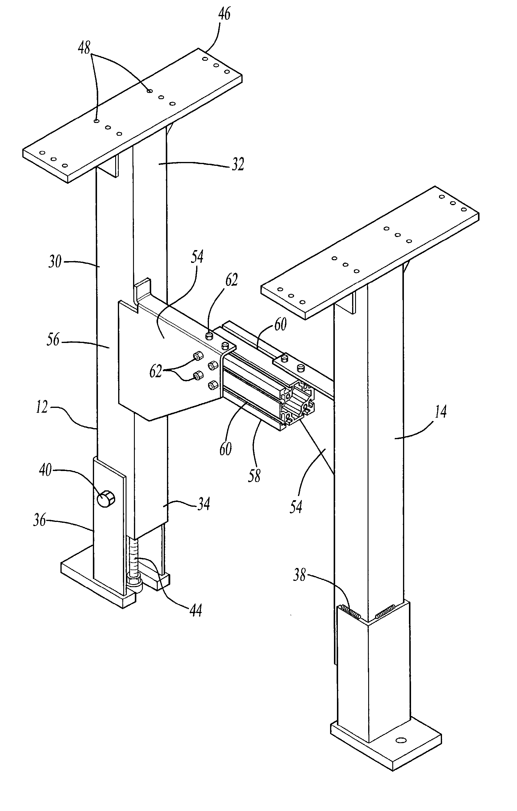
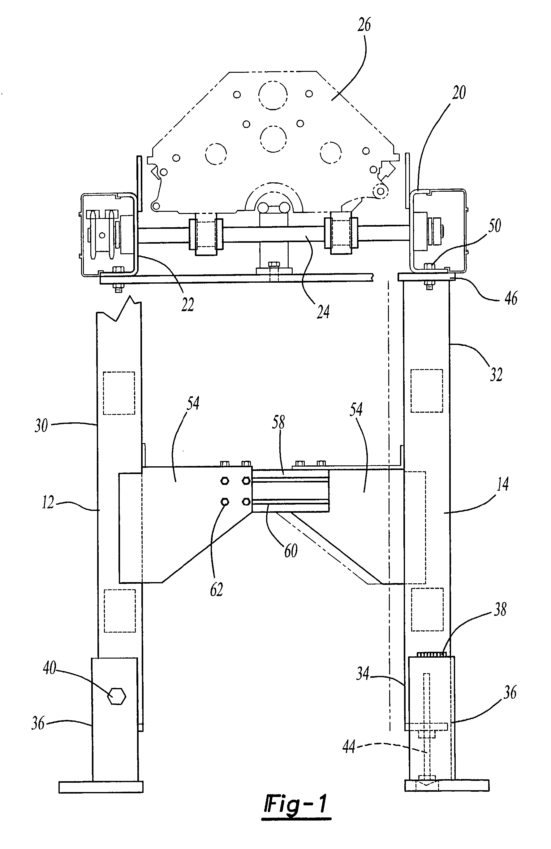
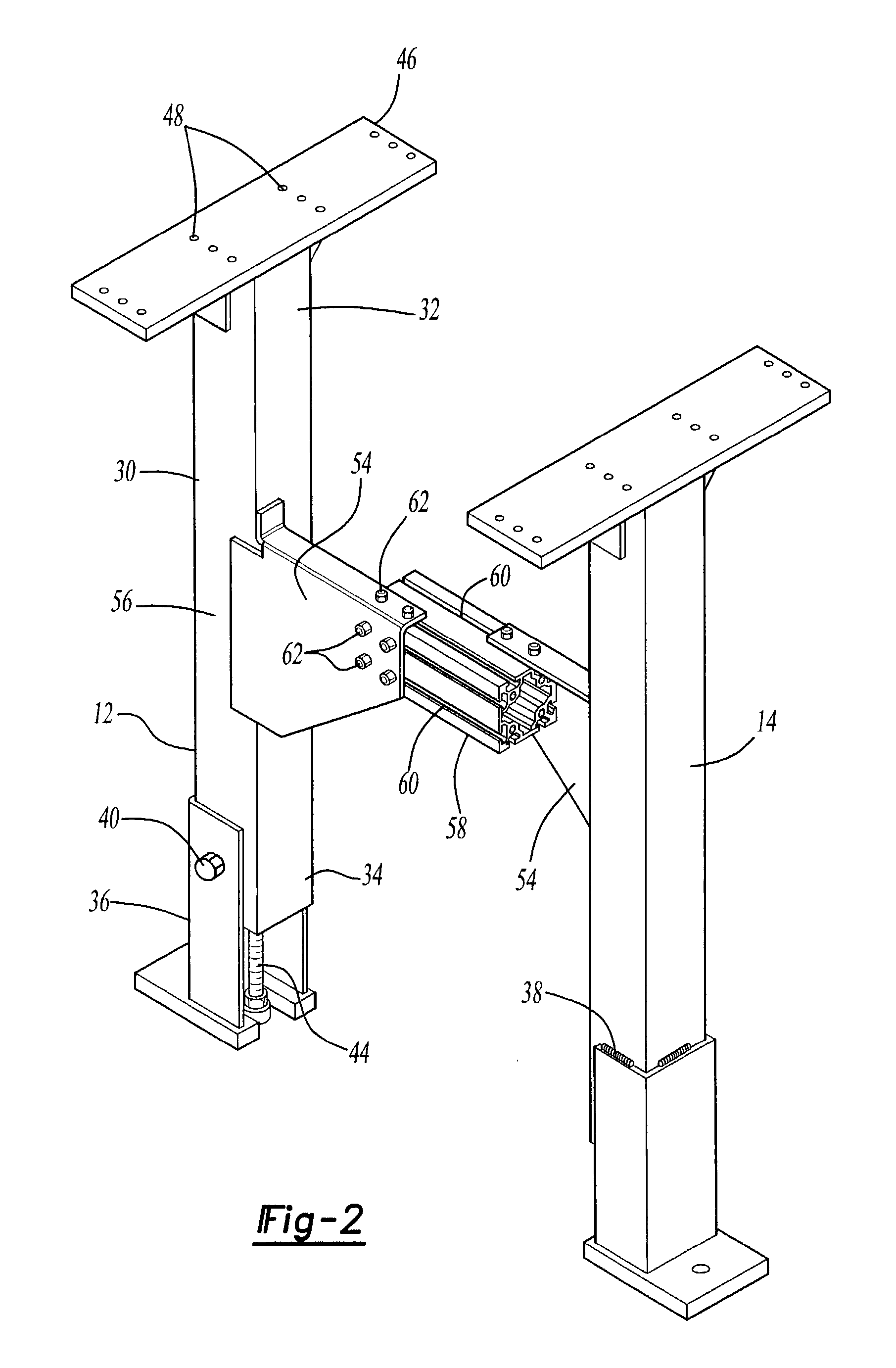
[0019] With reference first to FIG. 4, a preferred embodiment of the roller conveyor system 10 of the present invention is there shown and comprises a first pair of elongated vertical supports 12 and 14 and a second pair of elongated vertical supports 16 and 18. The first pair of vertical supports 12 and 14 are spaced from the second pair of vertical supports 16 and 18.

[0020] A first elongated rail 20 is disposed along and supported by an upper end of the vertical supports 14 and 18. Similarly, a second elongated rail 22 is secured to and supported by an upper end of the other vertical supports 12 and 16 so that the rails 20 and 22 are spaced apart and parallel to each other. Preferably, the rails 20 and 22 are manufactured in preset modular lengths, such as ten foot or twelve foot lengths.

[0021] Still referring to FIG. 4, a plurality of roller assemblies 24 are disposed between and supported by the rails 20 and 22 so that the roller assemblies 24 are spaced apart and parallel to ea...


PUM


Abstract

A modular roller conveyor system is disclosed having a first and second pair of elongated vertical supports. The first pair of vertical supports are adjustably secured together so that the first pair of supports are spaced apart and parallel to each other at a user selected spacing between the first pair of vertical supports. Similarly, the second pair of vertical supports are also adjustably secured together so that the second pair of vertical supports are spaced apart and parallel to each other at the same user selected spacing. A first elongated rail is then secured to the upper end of one of the first pair of vertical supports and to the upper end of one of the second pair of vertical supports. A second rail is then secured to the upper end of the other of both the first and second pair of vertical supports so that the rails are spaced apart and parallel to each other. A plurality of spaced roller assemblies are then disposed between and supported by the rails thus forming the conveyor path along which articles are conveyed.

Description

[0001] This application a continuation of U.S. patent application Ser. No. 09 / 730,305 filed Dec. 5, 2000.[0002] I. Field of the Invention[0003] The present invention relates generally to conveyor systems and, more particularly, to a modular roller conveyor system.[0004] II. Description of the Prior Art[0005] There are many previously known roller conveyor systems of the type used in industrial manufacturing operations. These previously known roller conveyor systems typically comprise an elongated frame having a pair of spaced apart and parallel rails. A plurality of roller assemblies are then disposed across the rails and spaced apart from each other thus forming the conveyor path upon which articles to be conveyed are supported.[0006] A primary disadvantage of this type of previously known industrial roller conveyor system is that each roller conveyor system has been custom designed and manufactured in dependence upon the particular type and size of article to be conveyed along the...

Claims


Application Information

Patent Timeline
Patent Type & Authority Applications(United States)
IPC IPC(8): B65G13/12B65G21/06
CPCB65G13/12B65G21/06
Inventor MCTAGGART, MICHAEL DOUGLASNOESTHEDEN, ANDREW
Owner VALIANT CO LTD
Why Eureka
Try Eureka