Machine and system for power generation through movement of water

a technology of power generation and movement, applied in the direction of fluid couplings, electric generator control, other chemical processes, etc., can solve the problems of large scale construction, inability to manufacture and replace, and difficult to easily configure the system for different settings, etc., to achieve low cost, easy to manufacture and replace, and topographic configurable

Inactive Publication Date: 2005-11-10
HYDRO GREEN ENERGY LLC
View PDF53 Cites 17 Cited by
  • Summary
  • Abstract
  • Description
  • Claims
  • Application Information

AI Technical Summary

Benefits of technology

[0007] A water driven turbine is used to extract electrical energy from the moving water (wave, current, tidal or other). A turbine fan will rotate independently in a converging nozzle to extract additional energy from moving water after each independent turbine fan. The fan blades rotate independently inside of a housing. The housing contains windings made of copper or a conductive polymer or other conductive material. Rotating magnetic field produced from a magneto polymer, particulate materials that generate a magnetic field suspended in a homogeneous or heterogeneous polymer or traditional magnetic material such as Fe, Co Ni, Gd, Sn, Nd or ceramics that exhibit magnetic fields generates electrical energy as the independent turbine containing the magnetic material passes by the conductive windings. The magneto polymer differs in that the magnetic characteristic exists at the atomic level as opposed to a particulate mixture suspended in a polymer. The truss structure in the polymer housing is composed of polymer or fiberglass reinforced polymer, carbon composite or nanotube reinforced polymer. The truss structure supports the central shaft of the turbine blade assembly inside of the polymer turbine housing. Electrical energy that is generated in each turbine should be in the range of 0.001-5,000 watts (W) but could be as large as 100,000 W per turbine. The electrical energy is transferred from the winding of each turbine and connected in parallel to a power transfer conduit internal to each of the turbine housings composed of copper wire or electrically conductive polymer. The power is transferred from one turbine housing to the next via the internal conduit until it can be transferred to a collection system for metering and eventual transfer to the grid. If one generator generates between 0.001-100,000 W, then a plurality of generators connected in parallel in a two dimensional array has the potential to generate commercial quantities in the multiple megawatt (MW) range. Since this system is made of polymer, ceramic or nonferrous coated metal, and any potentially magnetic part internal to the turbine does not contact the water directly, it does not corrode, it is light weight, it is portable, it is cheap to manufacture and replace and topographically configurable. Additionally, the array's modular (cellular) design allows for repairs and maintenance of the turbines without taking the entire power generating capacity of the array offline. Realistically, only a fractional amount of power generating capacity would be taken offline at any one time as only individual vertical stacks in the two dimensional array would be taken offline for maintenance of a turbine in that stack.

Problems solved by technology

The deficiency in the prior art is that the systems are not easily configurable for different settings, require large scale construction and are not commercially viable.
They are not suitable to being moved easily, they are not topographically adaptable, nor do they withstand the corrosive effects of water.
Further, the weight needed for a traditional generator having magnets and copper wire inhibits replacement.
Moreover, there has been no system using an array of small power cells arranged in parallel to capture the movement of the ocean, rivers or other current in such a way as to combine relatively small generators into one large power production system.

Method used


Image

  • Machine and system for power generation through movement of water
  • Machine and system for power generation through movement of water
  • Machine and system for power generation through movement of water

Examples


Embodiment Construction

[0026] Detailed descriptions of the preferred embodiment are provided herein. It is to be understood, however, that the present invention may be embodied in various forms. Therefore, specific details disclosed herein are not to be interpreted as limiting, but rather as a representative basis for teaching one skilled in the art to employ the present invention in virtually any appropriately detailed system, structure or manner.

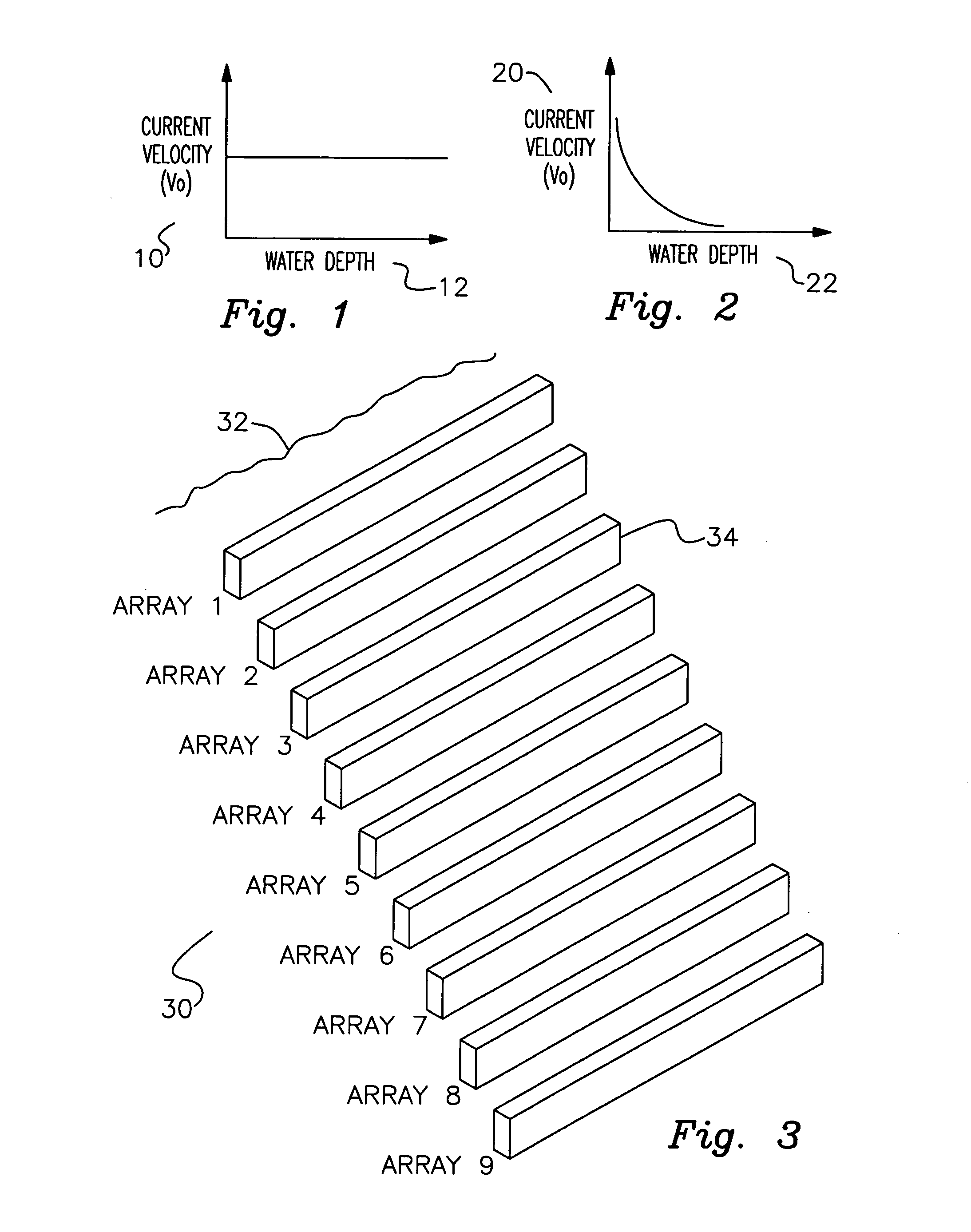
[0027] Turning now to FIG. 1, there is shown a graph depicting average or mean current velocity 10 as a function of water depth 12 in the ocean deepwater zone. It is observed that velocity is relatively constant in deepwater zones, between some upper and lower limits, and for certain purposes may be a source of water energy applicable to the present invention. The Gulf Stream in the Atlantic Ocean and Kuroshio Current in the Pacific Ocean provide examples of steady deepwater current that the present invention could utilize to drive a plurality of cells arrayed ...


PUM


Abstract

A machine and system for power generation through movement of water having an array of power generating cells electrically interconnected, where the array is configured in an interchangeable modular fashion and the cells are positioned to receive kinetic energy from the movement of water to generate electricity through the movement of an electrical turbine within each cell. The individual turbines and cells may generate relatively small amounts of electricity and use polymer magnetics in the impellers and windings in the turbine to withstand ocean environments and are stacked on electrically conductive trays for ease of installation and replacement.

Description

STATEMENT REGARDING FEDERALLY SPONSORED OR DEVELOPMENT [0001] Not Applicable DESCRIPTION OF ATTACHED APPENDIX [0002] Not Applicable CROSS REFERENCE TO RELATED APPLICATIONS [0003] This is a continuation of pending application Ser. No. 10 / 851,604 filed May 21, 2004, which is related to provisional patent application No. 60 / 474,051 titled “A Machine for Power Generation through Movement of Water,” filed on May 29, 2003, which is hereby incorporated by reference as if fully set forth herein. FIELD OF INVENTION [0004] This invention relates generally to the field of power generation and more specifically to a machine and system for power generation through movement of water. BACKGROUND OF THE INVENTION [0005] Extraction of energy from water sources has been a desire of mankind for ages. Various methods involve water wheels, entrainment, and hydroelectric turbines. Prior attempts to convert ocean tidal movements or current into power involve large scale systems, the use of traditional gen...

Claims


Application Information

Patent Timeline
Patent Type & Authority Applications(United States)
IPC IPC(8): F03B13/10F03B13/26F03B17/06F16D31/02
CPCF03B13/10F03B13/264F03B17/061Y10S415/906F05B2240/97Y02E10/28Y10S416/04F05B2240/40Y02E10/30F16D31/02Y02E10/20
Inventor KROUSE, WAYNE F.
Owner HYDRO GREEN ENERGY LLC
Why Eureka
Try Eureka