Depolarizer and spectroscope

a depolarizer and spectrometer technology, applied in the field of depolarizers and spectrometers, can solve problems such as difficulty in measuring the true central wavelength of ligh

Inactive Publication Date: 2003-01-09
ANDO ELECTRIC CO LTD
View PDF5 Cites 18 Cited by
  • Summary
  • Abstract
  • Description
  • Claims
  • Application Information

AI Technical Summary

Problems solved by technology

Therefore, because the diffraction efficiency varies according to the polarization state of the incident light in the spectroscope using the diffraction grating, a trouble occurs on measuring a spectroscopic characteristic of the incident ...

Method used


Image

  • Depolarizer and spectroscope
  • Depolarizer and spectroscope
  • Depolarizer and spectroscope

Examples


first embodiment

[0056] At first, a depolarizer according to a first embodiment of the present invention will be explained with reference to FIGS. 1A to 2D-S.

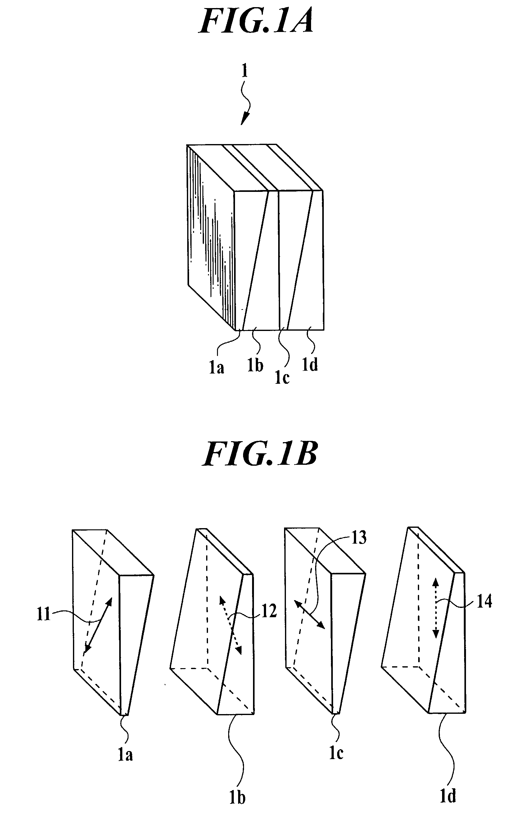
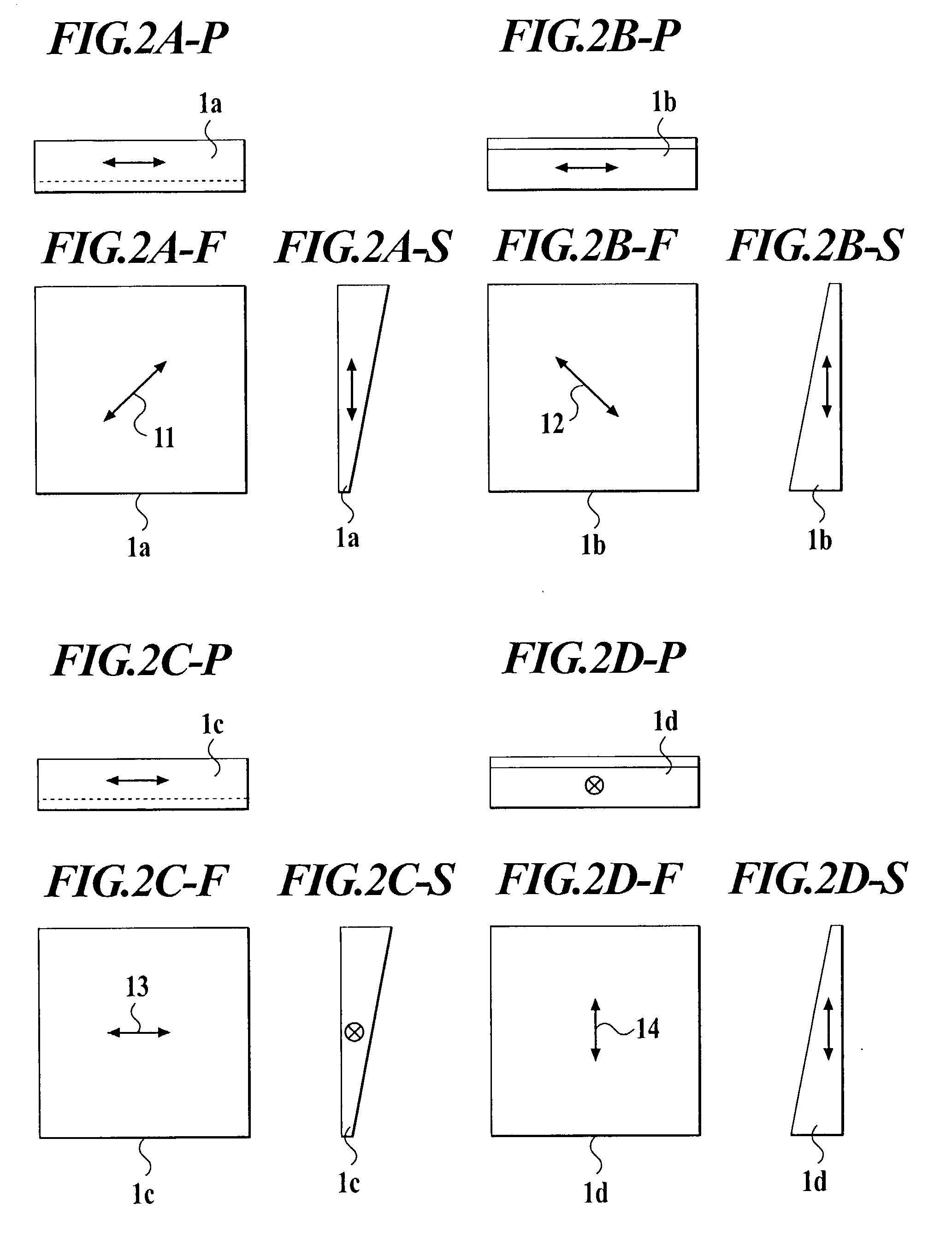
[0057] FIG. 1A is an external perspective view of a depolarizer 1, and FIG. 1B is an exploded perspective view of the depolarizer 1. FIGS. 2A-F, 2A-P and 2A-S are a front view, a plan view and a side view of a crystal plate 1a, FIGS. 2B-F, 2B-P and 2B-S are a front view, a plan view and a side view of a crystal plate 1b, FIGS. 2C-F, 2C-P and 2C-S are a front view, a plan view and a side view of a crystal plate 1c, and FIGS. 2D-F, 2D-P and 2D-S are a front view, a plan view and a side view of a crystal plate 1d, of the depolarizer 1.

[0058] A reference numeral 1 denotes a depolarizer. Reference numerals 1a, 1b, 1c and 1d denote crystal plates. Reference numerals 11, 12, 13 and 14 denote optical axes of the crystal plates 1a, 1b, 1c and 1d, respectively.

[0059] The depolarizer 1 comprises a crystal plate 1b as a first plate, a crystal plate 1c as a...

second embodiment

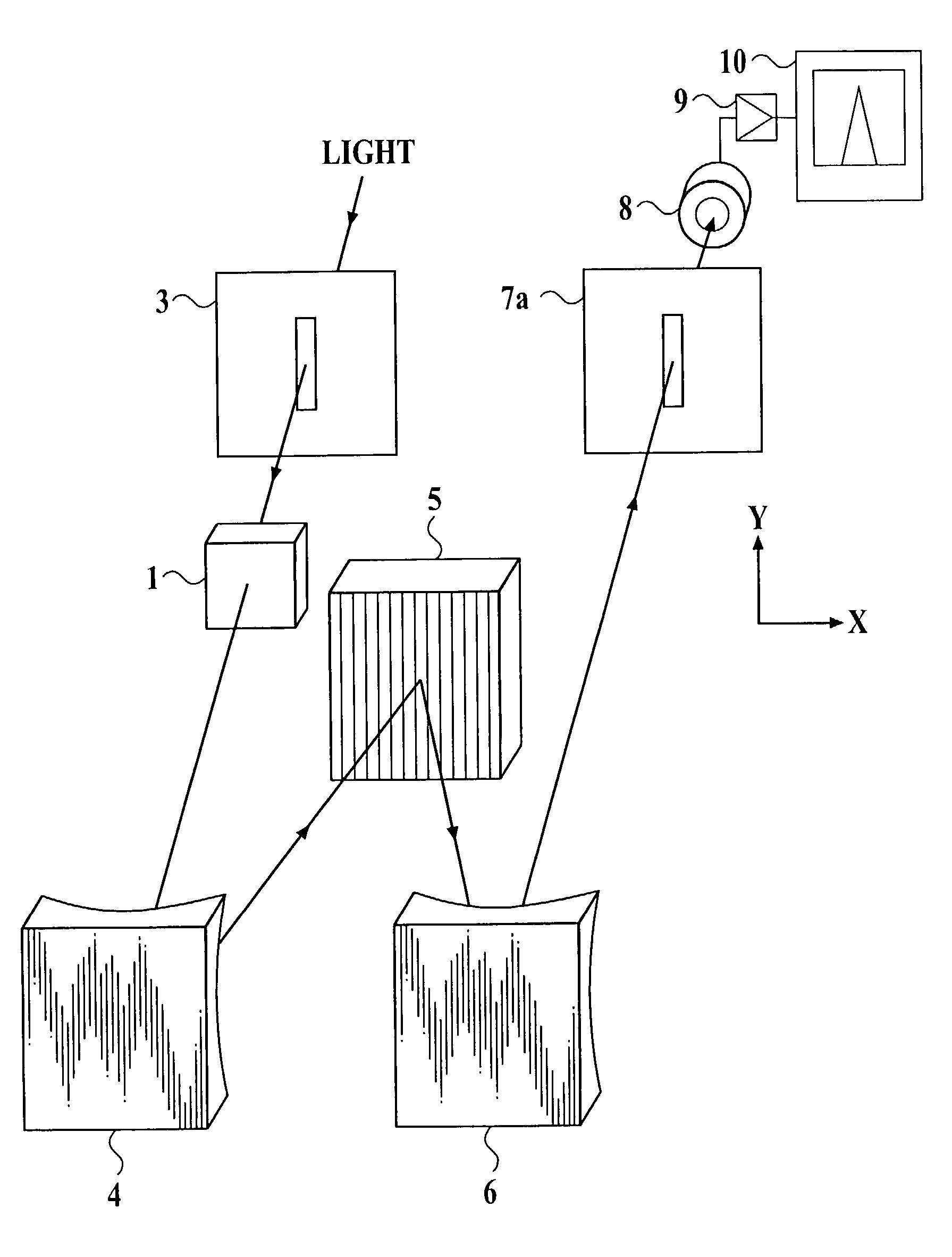
[0082] Next, a second embodiment of the present invention will be explained, as follows. Although the first embodiment has been explained with the outgoing slit 7a wherein the four light rays L7, L8, L9 and L10 pass through the focal points F6, F8, F7 and F9 as shown in FIGS. 8 and 9, the present second embodiment will be explained with an outgoing slit 7b as shown in FIG. 10 instead of the outgoing slit 7a.

[0083] The rectangular opening of the outgoing slit 7b is a slit that the rectangular opening of the outgoing slit 7a is shortened in the direction which has nothing to do with a wavelength selection. As shown in FIG. 10, the outgoing slit 7b cuts off two light rays L8 and L10 which travel to the focal points F8 and F9, respectively, and allows two light rays L7 and L9 which travel to the focal points F6 and F7 to pass therethrough. Therefore, because the two light rays L7 and L9 are selected as described above, it is unnecessary to relatively strengthen the powers of the light r...

third embodiment

[0086] Next, a third embodiment of the present invention will be explained, as follows. Although the first embodiment has been explained with the single path spectroscope which uses the diffraction grating shown in FIG. 3 at one time, the third embodiment will be explained with a multi path spectroscope which uses the diffraction grating at two or more times.

[0087] In other words, according to the first embodiment, the single path spectroscope is adopted so that the light passes through the diffraction grating which is the spectroscopic device, at one time. However, according to the third embodiment, the multi path spectroscope is adopted so that the light passes through the diffraction grating which is the spectroscopic device, at n times, and the depolarizer 1 is used in the spectroscope. As described above, when the depolarizer 1 is used in the multi path spectroscope, it is possible to obtain the following remarkable effects.

[0088] According to the third embodiment, ".alpha." is...


PUM


Abstract

A spectroscope having a high spectroscopic characteristic capable of eliminating a polarization dependence on an arbitrary polarization state of an incident light, and measuring a spectrum having a true central wavelength of the light. The spectroscope comprises: a depolarizer comprising: a first plate a thickness of which continuously changes in a direction of 45 degrees with a first optical axis; and a second plate a thickness of which continuously changes, and which is stuck on the first plate; wherein an angle between the first optical axis and a second optical axis of the second plate, is 45 degrees, and a first reduction direction of the thickness of the first plate and a second reduction direction of the thickness of the second plate is opposite to each other; and a spectroscopic device a dispersion direction of which intersects orthogonally with the first reduction direction.

Description

[0001] 1. Field of the Invention[0002] The present invention relates to a depolarizer used for eliminating a polarization dependence of a spectroscope.[0003] 2. Description of Related Art[0004] In general, a dispersion device used in a spectroscope has a polarization dependence. When such a light polarized in a particular direction, as a linearly polarized light, is incident on the dispersion device, even if the incident light has a given energy, the dispersion device has a particular output characteristics in accordance with the direction in which the incident light is polarized. A diffraction grating is a representative example of the dispersion device which is used in the spectroscope. The diffraction grating has the polarization dependence that is a diffraction efficiency varies with a polarization state of the incident light. In other words, a reflectance with the polarized light component perpendicular to a groove cut in the diffraction grating and a reflectance with the polar...

Claims


Application Information

Patent Timeline
IPC IPC(8): G01J3/18G01J3/02G02B27/28
CPCG01J3/02G01J3/0224G02B27/286
Inventor YAMAMOTO, TOSHIKAZUKANEKO, TSUTOMU
Owner ANDO ELECTRIC CO LTD
Why Eureka
Try Eureka