
Numerically controlled orbital machining apparatus

a technology of machining apparatus and control, which is applied in the direction of worms, milling equipment, large fixed members, etc., can solve the problems of occupying a relatively large space, affecting the precision of the machining results of holes, and the structure of the mechanism is somewhat complex

Inactive Publication Date: 2003-01-23
NOVATOR
View PDF6 Cites 40 Cited by
  • Summary
  • Abstract
  • Description
  • Claims
  • Application Information

AI Technical Summary

Benefits of technology

[0006] It is an object of the invention to provide an improved and structurally simpler and a more compact radial offset adjustment mechanism of the present invention which is configured to allow a continuous radial offset adjustment of the cutting tool while simultaneously performing an orbital movement thereof about the principal axis and moving it in an axial feed direction into the workpiece, thereby making it possible to produce not only cylindrical holes or recesses but also holes or recesses having a conical or tapered configuration or sections thereof by using a substantially cylindrically shaped cutting tool.
[0012] A further object of the invention is to provide a radial offset adjustment mechanism of the kind mentioned above, wherein the basic structural configuration of the radial offset adjustment mechanism is such as to allow for an accurate mass balancing of the centrically and eccentrically rotating (orbiting) components of the machining apparatus so that vibrations are eliminated or substantially attenuated during working operations of the apparatus.

Problems solved by technology

Although the radial offset adjustment mechanism is configured such as to make it possible to change the radial offset during machining such that conical holes may be formed while simultaneously rotating the cutting tool about its own center axis and feeding the cutting tool axially into the workpiece, this mechanism is somewhat structurally complex and occupies a relatively large space in the longitudinal direction.
The spindle motor is protruding substantially in a cantilevered manner from supporting structures of the apparatus, which may affect the precision of the machining results of the holes produced thereby.

Method used


Image

  • Numerically controlled orbital machining apparatus
  • Numerically controlled orbital machining apparatus
  • Numerically controlled orbital machining apparatus

Examples


Embodiment Construction

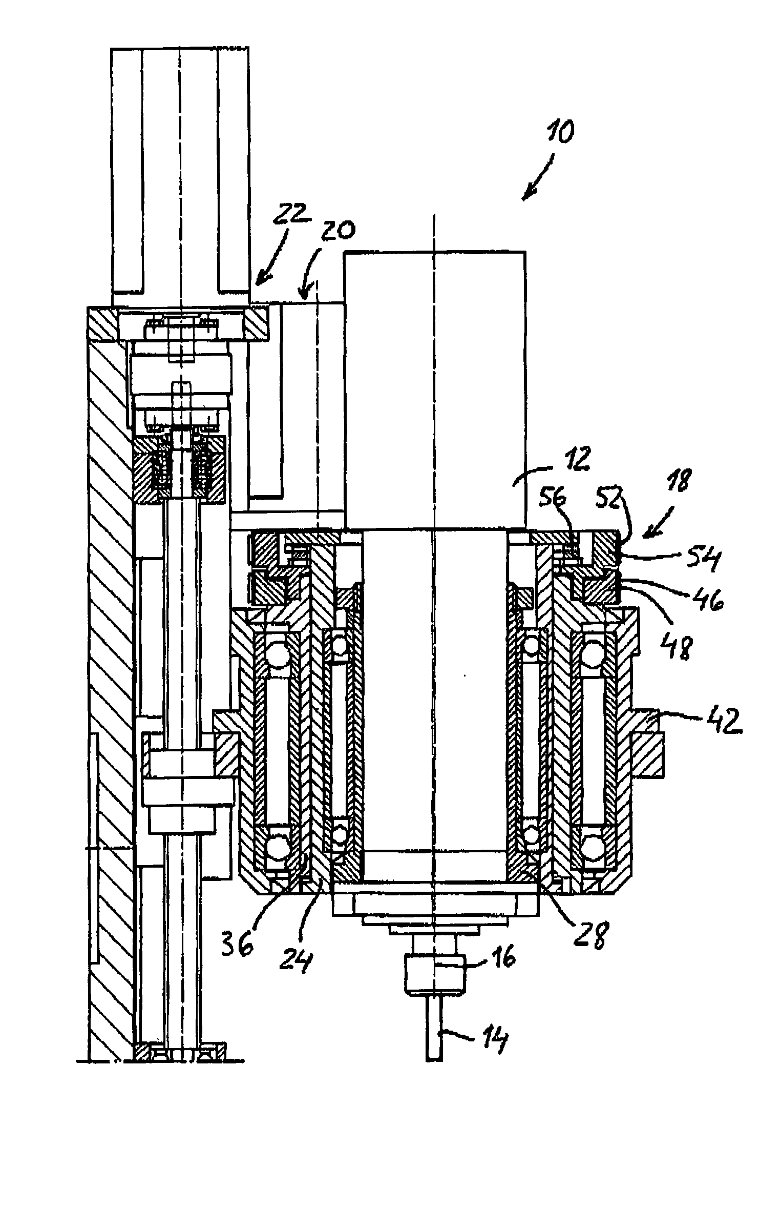
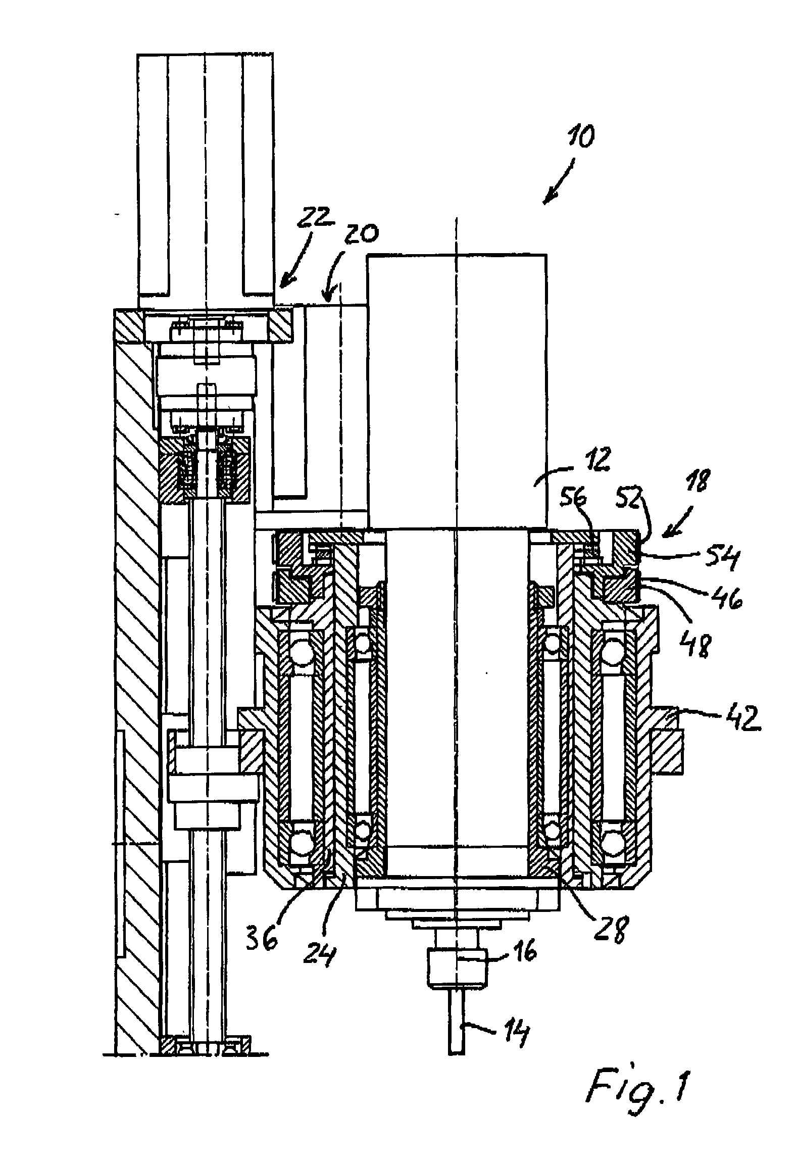
[0021] As shown in FIG. 1, the orbital machining apparatus 10 generally includes a spindle motor unit 12 that rotates a cutting tool 14 about its own axis 16, a radial offset mechanism 18, an eccentric rotation mechanism 20 and an axial feed mechanism 22. The apparatus 10 may be mounted in a stationary stand or mounted to a movable member, such as a robot arm.

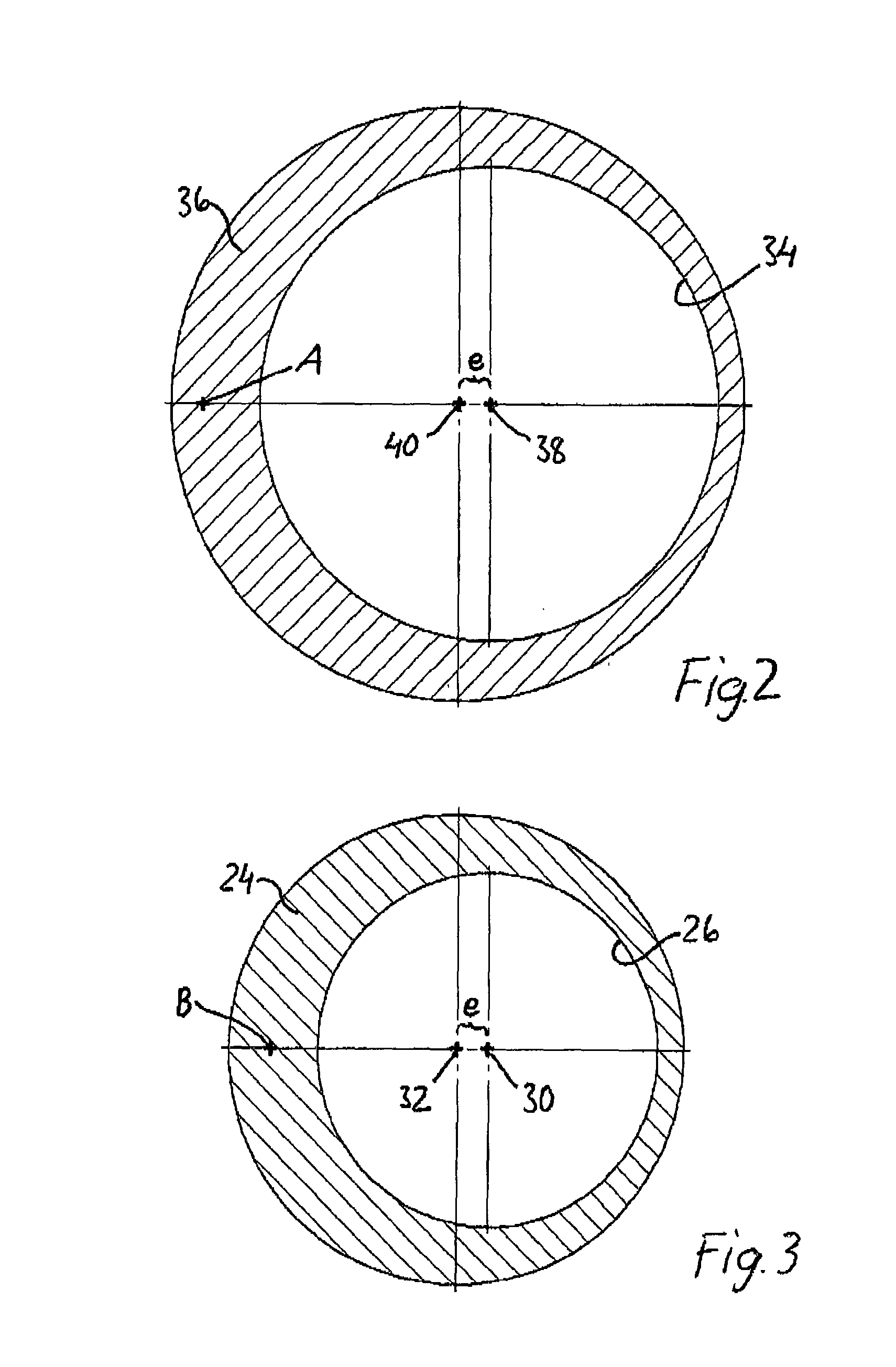
[0022] The radial offset mechanism 18 of the invention basically includes an inner hollow cylindrical body 24 rotatably supporting the spindle unit 12 therein. The spindle motor unit 12 is rotatably supported in an eccentric cylindrical hole 26 (FIG. 3) in the cylindrical body 24 via a fixation sleeve 28 (FIG. 1). The eccentric hole 26 has a longitudinal center axis 30 (FIG. 3) that is parallel to but radially offset a distance e from the longitudinal center axis 32 of the cylindrical body 24.

[0023] The eccentric inner cylindrical body 24 is, in its turn, rotatably supported within an axially extending eccentric hole 34 of a se...


PUM

PropertyMeasurementUnit
radial distanceaaaaaaaaaa
distanceaaaaaaaaaa
gravityaaaaaaaaaa

Abstract

An orbital machining apparatus for producing a cylindrical or conical hole in a workpiece includes a cylindrical cutting tool. The apparatus includes a radial offset mechanism configured for controlling the radial distance of the center axis of the cutting tool from a principal axis, the principal axis being substantially parallel to the center axis of the tool and coaxial with a longitudinal center axis of the hole to be machined. The radial offset mechanism includes an inner cylindrical body having an eccentric cylindrical hole, the eccentric hole having a longitudinal center axis that is parallel to and radially offset from a longitudinal center axis of the inner body, the eccentric hole being configured to radially and rotatably support a spindle unit for operating the cutting tool; and an outer cylindrical body having an eccentric cylindrical hole, the eccentric hole of the outer body having a longitudinal center axis that is parallel to and radially offset from a longitudinal center axis of the outer body a distance which is equal to the distance between the center axis of the eccentric hole of the inner body and the center axis of the inner cylindrical body, the inner cylindrical body being radially supported in the eccentric hole of the outer cylindrical body and rotatable therein so as to adjust the radial distance of the center axis of the cutting tool from the principal axis.

Description

CROSS REFERENCE TO RELATED APPLICATIONS[0001] This is a non-provisional application based upon U.S. provisional patent application serial No. 60 / 306,844, entitled "NUMERICALLY CONTROLLED SPINDLE UNIT FOR ORBITAL DRILLING", filed Jul. 20, 2001.BACKGROUND OF THE INVENTION[0002] 1. Field of the Invention.[0003] The invention generally relates to a numerically controlled orbital machining apparatus for producing a hole in a workpiece by means of a cutting tool rotating about its own tool axis as well as eccentrically (orbiting) about a principal axis corresponding to the longitudinal center axis of the hole to be machined. More particularly, the invention relates to an improved mechanism of the apparatus for adjusting the radial offset (orbit radius) of the cutting tool axis relative to the principal axis.[0004] 2. Description of the Related Art.[0005] WO 99 / 62661 discloses an apparatus for machining a hole in a workpiece wherein the apparatus includes a spindle motor that rotates a cut...

Claims


Application Information

Patent Timeline
Patent Type & Authority Applications(United States)
IPC IPC(8): B23Q1/48B23C1/06B23Q1/54
CPCB23Q1/4885B23Q1/5468B23B41/06Y10T409/307616Y10T409/307056Y10T409/30056B23B2265/12B23C2220/52B23C3/02
Inventor LINDERHOLM, DAG G.ROSWALL, GORANNYGREN, JOAKIM
Owner NOVATOR
Learn More