Magnetic tape apparatus

Inactive Publication Date: 2003-01-30
NEC CORP
View PDF0 Cites 11 Cited by
  • Summary
  • Abstract
  • Description
  • Claims
  • Application Information

AI Technical Summary

Problems solved by technology

Conventionally, in a magnetic tape apparatus that uses a tape cartridge containing a magnetic tape, unless the motive power for pulling out the magnetic tape from the tape cartridge is obtained from a reel motor, the structure becomes complicated.
However, the structure disclosed in Japanese Patent Publication No.2001-135003 has the following problems.
Thus, the number of parts necessary for the apparatus becomes large.
As a third problem, since the loader and the arm are driven by the same motor, a high power motor is necessary for it, so that the cost of the apparatus will increase.
In other words, when the mechanism of which the tape is pulled out to the reel by the motive power

Method used


Image

  • Magnetic tape apparatus
  • Magnetic tape apparatus
  • Magnetic tape apparatus

Examples


Embodiment Construction

[0025] Next, with reference to the accompanying drawings, an embodiment of the present invention will be described.

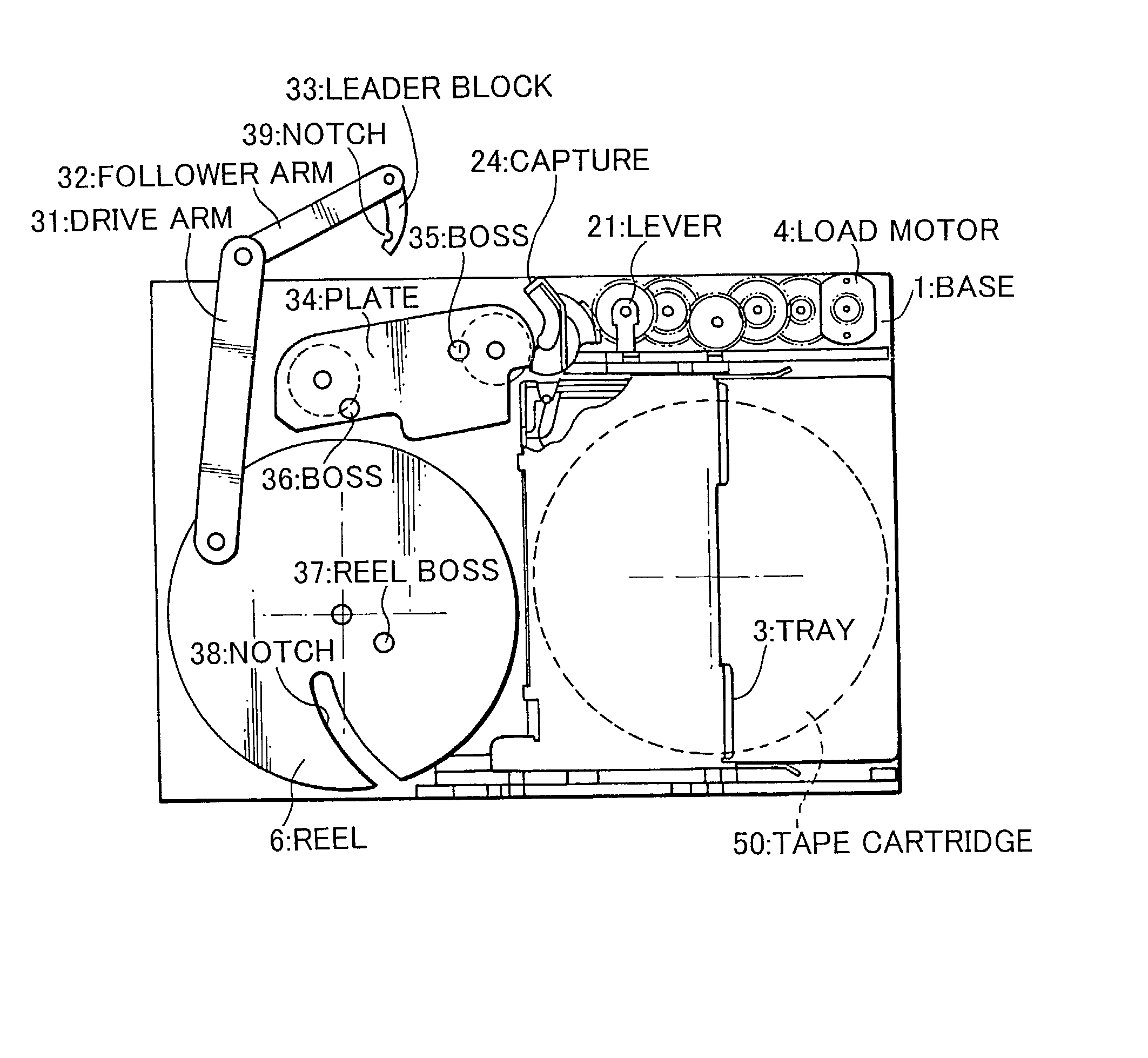
[0026] FIGS. 4A and 4B are a side view and a plane view showing the structure of a magnetic tape apparatus according to the present invention, respectively. FIGS. 5A and 5B are a side view and a plane view showing the structure of a tape cartridge for use with the magnetic tape apparatus according to the present invention. The tape cartridge is denoted by reference numeral 50. The tape cartridge 50 contains a tape 51 on which data is magnetically recorded. A pin 52 is disposed at a tip of the tape 51. The pin 52 is used to pull out the tape 51 from the tape cartridge 50.

[0027] With reference to FIGS. 4A and 4B, the magnetic tape apparatus according to the present invention has a loader 2 that places the tape cartridge 50 on a base 1. The base 1 has a reel 6 and a motor 5. The tape 51 is wound around the reel 6. The motor 5 rotates the reel 6. A drive arm 31 is disposed ...


PUM


Abstract

A magnetic tape apparatus according to the present invention has a reel and a motor. A tape is wound on the reel. The motor rotates the reel. A drive arm is disposed on the reel. A follower arm is disposed on the drive arm. The follower arm has a rotatable leader block. The leader block also has a notch for hooking a pin of the tape. As a load motor is rotated, a loader is moved. The loader places a tape cartridge that is inserted from the outside at a predetermined position of a base. At that point, a motive power of the load motor is transferred to a capture gear. A capture that rotates the leader block is connected to the capture gear.

Description

[0001] 1. Field of the Invention[0002] The present invention relates to a magnetic tape apparatus that performs magnetic recording / reproducing operations using a tape cartridge that contains a magnetic tape.[0003] 2. Description of the Related Art[0004] Conventionally, in a magnetic tape apparatus that uses a tape cartridge containing a magnetic tape, unless the motive power for pulling out the magnetic tape from the tape cartridge is obtained from a reel motor, the structure becomes complicated.[0005] For example, Japanese Patent Publication No.2001-135003 discloses a mechanism that uses a load motor as a motive power source. FIG. 1 shows the structure of the mechanism. The load motor rotates a gear 111 in a direction B. A groove 122 of the gear 111 causes a boss 121 disposed on a tray 103 to be moved in a direction D. As a result, the tray 103 is moved. A gear 112 connected to the gear 111 is rotated in a direction C. A boss 123 disposed on an arm 131 is moved along a groove 124. ...

Claims


Application Information

Patent Timeline
IPC IPC(8): G11B15/67G11B23/26G11B15/675
CPCG11B15/67
Inventor MASUDA, TAKASHI
Owner NEC CORP
Why Eureka
Try Eureka