
Apparatus and method of remote gas trace detection

a gas trace detection and apparatus technology, applied in the direction of optical radiation measurement, instruments, spectrometry/spectrophotometry/monochromators, etc., can solve the problems of high cost of opo-based lidar, prone to alignment problems, complex opo systems, etc., and achieve large losses.

Inactive Publication Date: 2003-02-13
GAS TECH INST
View PDF0 Cites 80 Cited by
  • Summary
  • Abstract
  • Description
  • Claims
  • Application Information

AI Technical Summary

Problems solved by technology

On the other hand, OPO-based LIDAR is expensive and also requires extreme environmental controls to maintain stable long term operation.
OPO systems are complex and prone to alignment problems, requiring highly trained maintenance personnel.
Also, since OPO-based LIDAR emits pulses of laser light, the pulse repetition frequency (PRF) can present a significant problem for mobile applications seeking to detect small gas plumes, such as gas leak plumes.
The mobile platform is thus not only likely to miss some plumes entirely but also can incorrectly estimate plume concentrations as the OPO is tuned between wavelengths and the target moves relative to the OPO-based system.
Although the latter, moving-target problem can be reduced by using two OPO-based LIDARs that near simultaneously transmit differential wavelength pairs, this dual-OPO laser system is not only expensive but also very complex and does not solve the former, low PRF problem.
These systems, however, produce micro-joule energies due to the high PRF, requiring long integration times to accomplish detection.
For this reason, the system will likely miss small or low concentration plumes, particularly in the mobile environment.
These systems are also very expensive--probably too much so for use by pipeline survey companies--and they are difficult to maintain in alignment, especially in a mobile application.
This is because OPO-based systems require extreme environmental controls and stability to operate properly.
Field and mobile applications generally do not allow for these types of controls.
These frequency-mixing systems use expensive lasers (such as ND-YAG and Ti:Sapphire lasers in downconverting frequency mixing schemes or CO2 lasers in upconverting devices).
Like the OPO-based systems, they also are non-linear crystal-based systems that are difficult to maintain in alignment, especially in mobile applications.
Low frequency lock-in detection, however, has several major disadvantages for mobile, remote detection operations.
First, low frequency lock-in detection requires long scanning and data averaging times to achieve sufficient sensitivity to detect small remote plumes.
As a result, low frequency lock-in detection TDL LIDAR techniques are effectively limited to static line-of-sight, not mobile, applications.
Second, although there are other processing techniques such as matched filtering that can often be used in LIDAR systems to improve sensitivity, these techniques cannot be used with low frequency TDL LIDAR systems.
While there are lasers available, such as the OPO-based LIDARs described above, that operate within the fundamental absorption level and overtone band of gases such as methane, the applicants believe that such systems have not provided a solution to the problem of using LIDAR to economically and reliably detect gas leaks, particularly methane gas leaks, in mobile applications.
There have been TDL-based lasers in the prior art that operate in the first overtone band, but not in the fundamental absorption band, of gases such as methane, but they have not been applied to mobile detection of gases such as methane.
Because such lasers operate in only the overtone band, they are not as readily absorbed by gases such as methane.
Applicants believe that, as a result of this limitation and possibly other aspects of TDL-based lasers, such lasers have not been applied to the mobile detection of gases such as methane.
Although the '511 patent does suggest that FMS techniques may be used with a variety of lasers including TDL-based lasers, the '511 patent does not teach how to apply FMS techniques to any particular TDL apparatus.
The '511 patent also does not teach any mobile apparatus or method or use of FMS or TDL techniques to detect methane gas in particular, much less remotely detect methane gas in the atmosphere.

Method used


Image

  • Apparatus and method of remote gas trace detection
  • Apparatus and method of remote gas trace detection
  • Apparatus and method of remote gas trace detection

Examples


Embodiment Construction

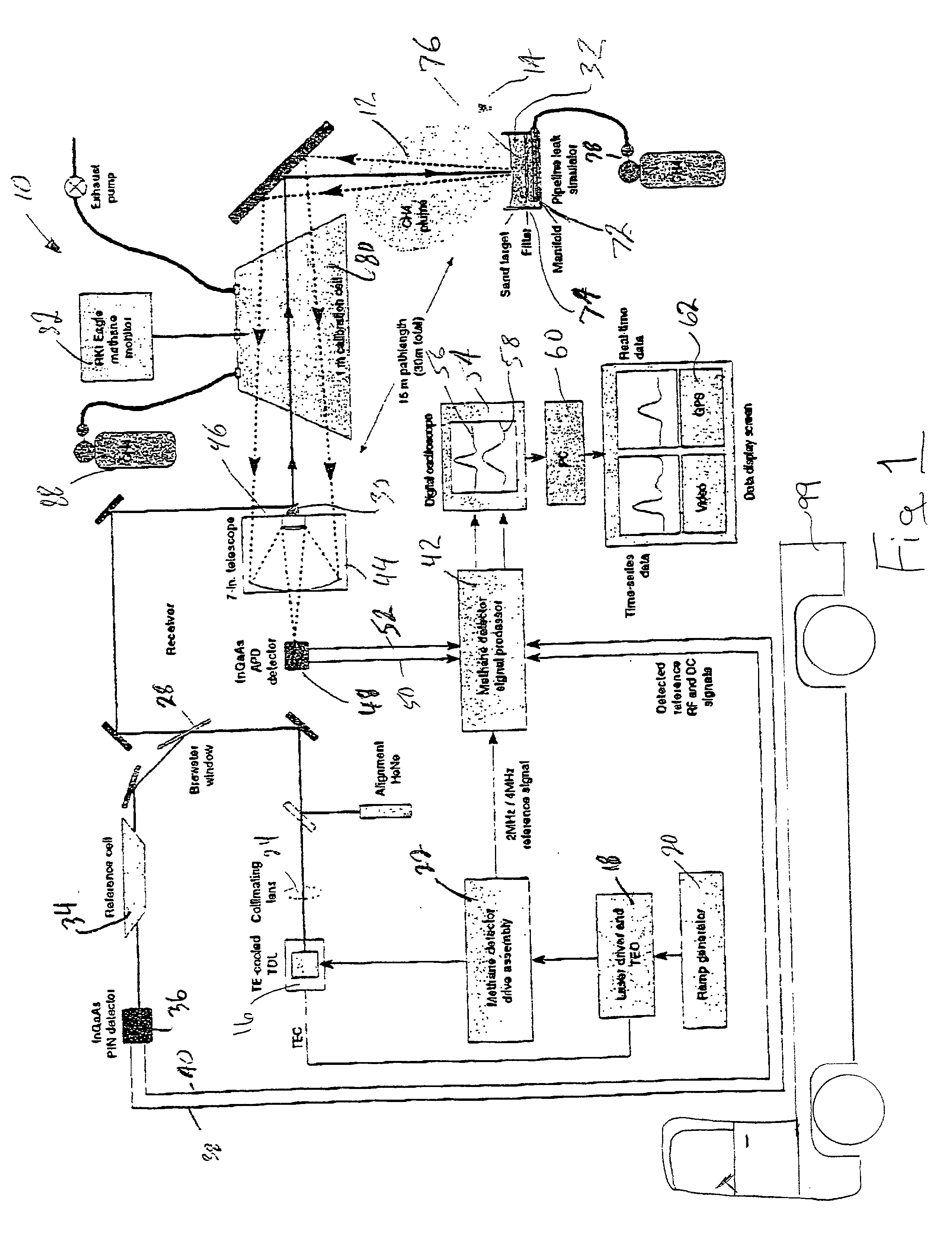
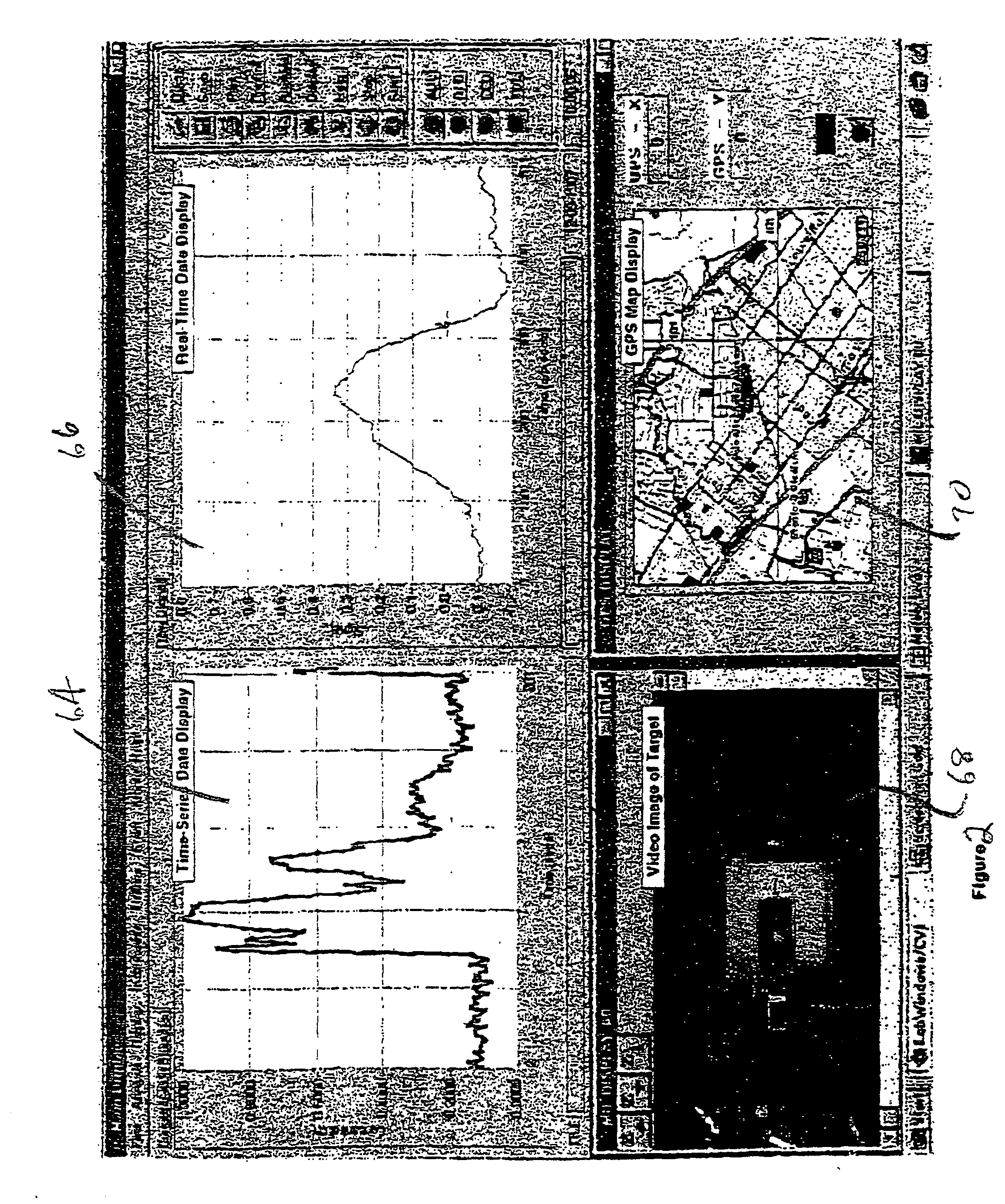
[0053] In order to test the apparatus 10, remote gas leak simulation was effected by disseminating methane through a manifold 72 over a 3 sq. inch area under a paper filter 74 underlying, and separating the manifold 72 from, a sand target 76 about one half inches deep. The methane needle valve 78 was opened for varying periods of time in order to simulate large and small gas leaks in the 10 to 300 p.p.m. range. The display shown in FIG. 2 is an example of the data collected during one such simulated gas leak.

[0054] In order to calibrate the response of the apparatus 10, a 10 inch diameter, 1 meter long sample chamber or reference cell 80 can be placed in the path of the laser light emitted from the output mirror 30. A pre-calibrated RKI EAGLE (TRADEMARK) methane monitor 82 is connected to the chamber in a manner well known to those skilled in the art. The methane monitor 82 provides an independent measurement of methane concentration in the cell as function of time during the test.

[...


PUM

PropertyMeasurementUnit
wavelengthaaaaaaaaaa

Abstract

This specification discloses a method and apparatus for the mobile and remote detection of a gas, such as methane, in the atmosphere. The apparatus includes a TDL based Light Detection and Ranging (LIDAR) driven at carrier frequency lying within the absorption line of the gas. The apparatus also drives the TDL with a modulation frequency to generate upper and lower sidebands in the output of the TDL and with a low ramp frequency to sweep the output of the TDL across twice the width of the pressure-broadened absorption line of the gas, preferably the first overtone absorption line in the case of methane detection. Suitable power for remote detection through use of the TDL is provided by a master oscillator / fiber amplifier transmitter has no moving or adjustable parts at all. An all-solid-state monolithic and integrated amplifier is achieved, which leads to a compact and virtually maintenance-free LIDAR system. The remote detection apparatus includes reference and calibration cells or chambers, and includes a light collector and detectors to detect the quantity and modulation of the light that passes the reference or calibration cells and that is received by the apparatus after reflection back toward the apparatus from an uncooperative target. The apparatus further includes a signal processor that applies a derivative spectroscopy technique, such as frequency modulation spectroscopy or wavelength modulation spectroscopy, to determine the presence of the gas in the atmosphere.

Description

[0001] This is a continuation of U.S. patent application Ser. No. 09 / 488,453, filed January 2000.[0002] This invention relates to the use of Light Detection and Ranging (LIDAR) to detect elements in the atmosphere remotely. More particularly, this invention relates to mobile use of modulated tunable diode lasers in order to sweep the laser wavelength through an absorption line of a gas such as methane in order to determine the presence of the gas in the atmosphere.[0003] LIDAR systems operate somewhat like radar. LIDAR, however, directs laser light rather than radar waves at a particular target to detect the target. The laser light may be pulsed or relatively continuously generated, and it may be focused or collimated as desired to reach the desired end. Objects, particles, and gases can scatter and / or absorb the laser light. Thus, the measurement of the reflected light can provide information about the target or atmospheric constituents along the optical path. LIDAR data is derived...

Claims


Application Information

Patent Timeline
Patent Type & Authority Applications(United States)
IPC IPC(8): G01J3/433G01N21/39G01N21/53
CPCG01J3/433G01N21/39G01N21/538G01N2021/1793
Inventor COOPER, DAVID E.VUJKOVIC-CVIJIN, PAJO
Owner GAS TECH INST
Learn More