Method and apparatus for removing flicker from images

a technology of flicker removal and image, applied in the field of image processing, can solve the problems of flicker period not being reduced below the flicker period, method described, and image artifacts appearing,

Active Publication Date: 2003-02-13
APTINA IMAGING CORP
View PDF11 Cites 55 Cited by
  • Summary
  • Abstract
  • Description
  • Claims
  • Application Information

AI Technical Summary

Problems solved by technology

If the period of the variation in the illumination level of the scene is longer than the integration period of the rolling shutter and shorter than the frame period, the variation will result in the appearance of image artifacts in the form of horizontal bands in the image.
The method described, however, does not apply to a situation wherein only a single image frame is available and wherein the flicker is manifested as a series of horizontal bands in th

Method used


Image

  • Method and apparatus for removing flicker from images
  • Method and apparatus for removing flicker from images
  • Method and apparatus for removing flicker from images

Examples


Embodiment Construction

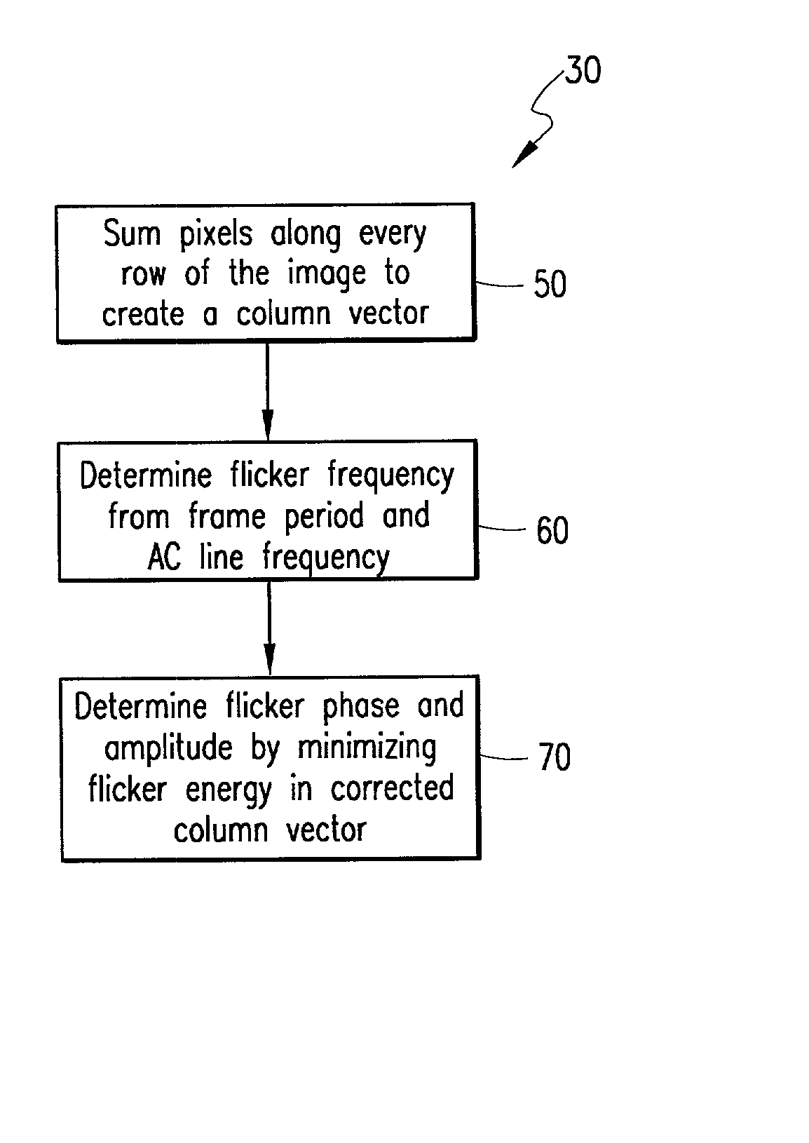
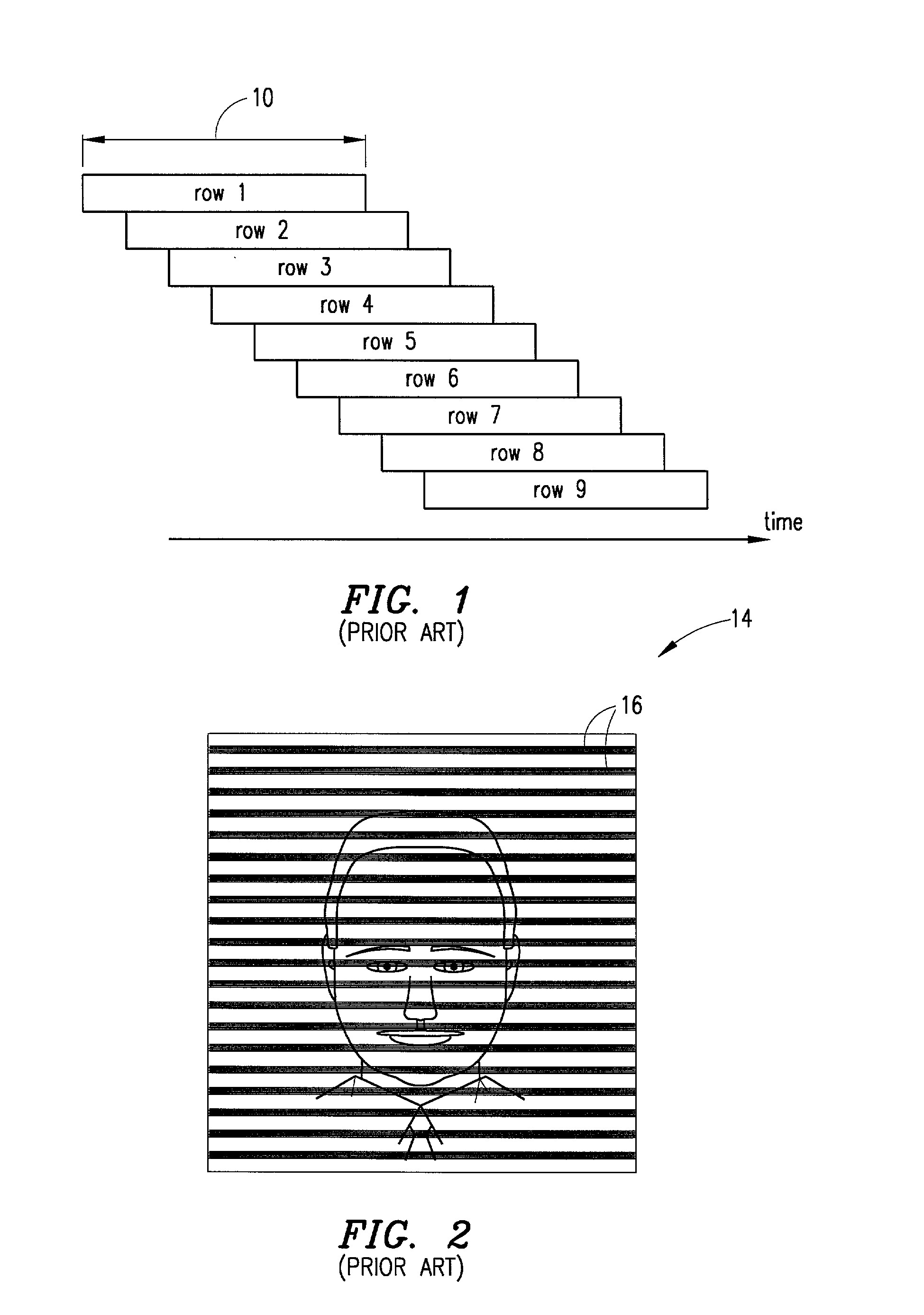
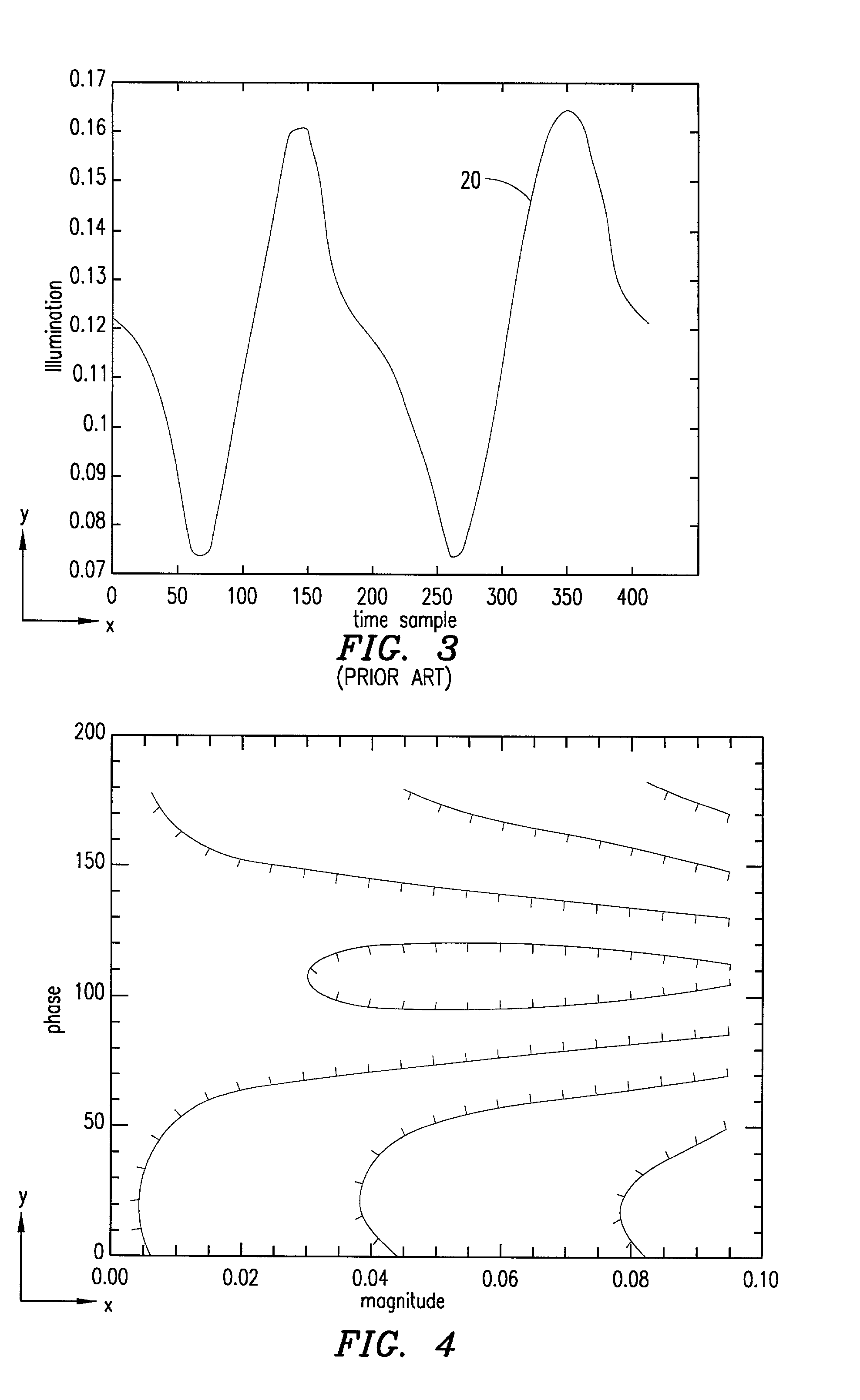
[0029] In a CMOS image sensor operating in a rolling shutter mode, the exposure interval of an image data array varies from row to row in the array as shown in FIG. 1 (although within a particular row, all pixels are exposed over the same interval). If the intensity of the light source illuminating a scene being imaged varies over time, row-to-row light intensity variations may result in the image data. If the row interval is fixed and the intensity of the light source varies periodically with time, the intensity variations will appear as image artifacts in the form of periodic horizontal bars in an image created from the image data.

[0030] If the integration period is made equal to an integer multiple of the flicker period, the amplitude of the horizontal bars will be zero. An a priori determination of the amplitude of the bars is generally not possible, however, because the characteristics of the light source are not known. In addition, the vertical alignment of the horizontal bar ...


PUM


Abstract

Method and apparatus for removing image artifacts from an image of a scene illuminated by a periodically varying light source such as a fluorescent light source. The image is represented by image data, and the method has the steps of determining a flicker function and processing the image data using the flicker function to remove the image artifacts from the image. The method and apparatus operate on data of a single image, do not require any additional input other than values of the flicker and frame periods, and do not require that the flicker be independently monitored. The method and apparatus is suitable for removing image artifacts from an image represented by image data collected by a CMOS image sensor utilizing a rolling shutter.

Description

[0001] 1. Technical Field of the Invention[0002] The present invention relates generally to the image processing field; and, more particularly, to a method and apparatus for removing image artifacts from images that are produced by a periodically varying light source.[0003] 2. Description of Related Art[0004] In a CMOS (Complementary Metal Oxide Semiconductor) active-pixel image sensor, a rolling shutter is commonly used to provide exposure control. A rolling shutter may be implemented by sequentially resetting each row of sensors in an image sensor array and sequentially reading the values of each row at a later time. The exposure period is equal to the interval between reset and read out, and the frame period is the time required to read the values of every row in the array.[0005] FIG. 1 is a diagram that schematically illustrates the operation of a rolling shutter to assist in providing a clear understanding of the present invention. Consider an image data array having 100 rows (...

Claims


Application Information

Patent Timeline
IPC IPC(8): H04N5/217H04N5/21H04N5/235H04N5/243H04N5/351H04N5/374
CPCH04N5/217H04N5/23229H04N5/235H04N5/2357H04N23/81H04N23/80H04N23/745H04N23/70
Inventor BAER, RICHARD L.
Owner APTINA IMAGING CORP
Why Eureka
Try Eureka